The controller requires an external 12 or 24VDC power supply, according to the controller model.
Exact information may be found in the controller’s technical specification sheet.
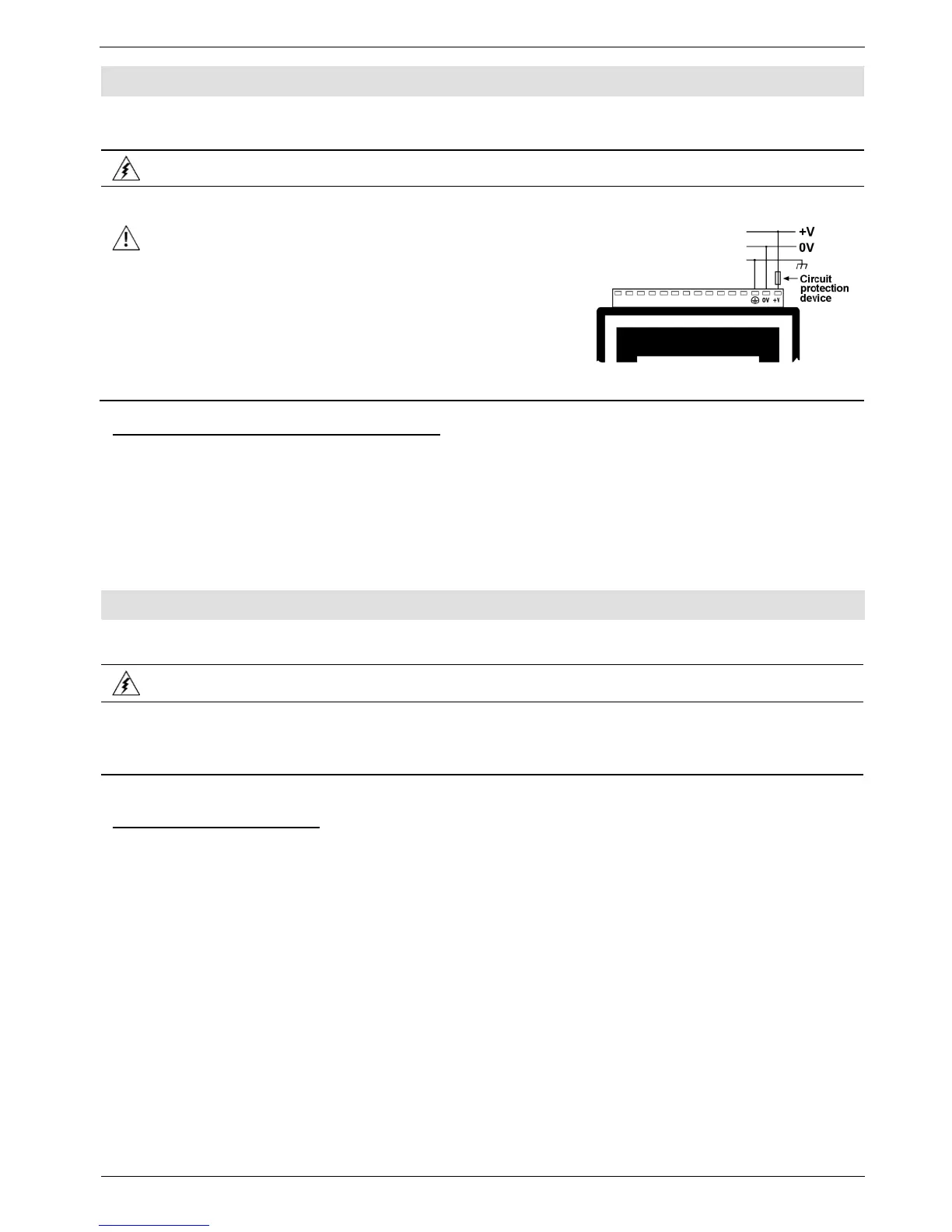
A non-isolated power supply can be used if a 0V signal is connected to the chassis.
You must use an external circuit protection device.
Install an external circuit breaker. Guard against short-
circuiting in external wiring.
Double-check all wiring before turning on the power
supply.
Do not connect either the ‘Neutral or ‘Line’ signal of the
110/220VAC to device’s 0V pin.
In the event of voltage fluctuations or non-conformity to
voltage power supply specifications, connect the device
to a regulated power supply.
M91 only: Earthing the Power Supply
To maximize system performance, avoid electromagnetic interference by:
Mounting the controller on a metal panel.
Earthing the controller’s power supply: connect one end of a 14 AWG wire to the chassis
signal; connect the other end to the panel.
Note: The wire used to earth the power supply must not exceed 10 cm in length. If your
conditions do not permit this, do not earth the power supply
Note that different controller models offer different serial and CANbus communication options. To
see which options are relevant, check your controller’s technical specifications.
Turn off power before making communications connections.
Note that the serial ports are not isolated.
Signals are related to the controller’s 0V; the same 0V is used by the power supply.
Always use the appropriate port adapters.
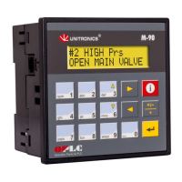
Both M90 and M91 comprise an RJ-11 type serial port that supports RS232.
An M91 serial port can be set to either RS232 or RS485 according to jumper settings.
Use RS232 to download programs from a PC, and to communicate with serial devices and
applications, such as SCADA.
Use RS485 to create a multi-drop network containing up to 32 devices.