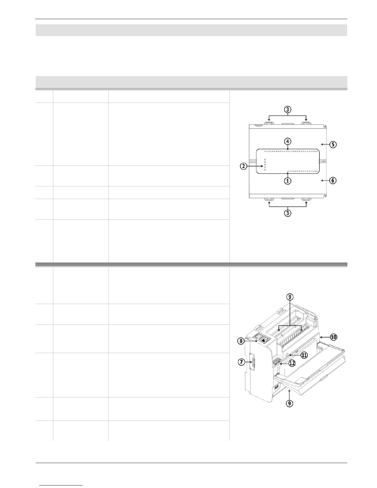
EasyManuals Logo

Unitronics UniStream PLC Series User Manual

Unitronics UniStream PLC Series
12 pages
To Next Page IconTo Next Page
To Previous Page IconTo Previous Page
Page #4 background imageLoading...
Page #4 background image
UniStream
®
PLC
Kit Contents
1 UniStream PLC
1 power terminal block
3 I/O terminal blocks (provided only with
models comprising built-in I/Os)
1 Battery
Product Diagram
1
Output LEDs
Green / Red LEDs
Front View
2 Status LEDs Tricolor LEDs, Green/Red/Orange
From top to bottom: RUN,
ERROR, USB, BATT. LOW, and
FORCE.
Note that LED indications are
listed in the product's technical
specifications.
3 DIN-rail clips Clips at top and bottom
physically support the device
4
Input LEDs
Green / Red LEDs
5 Top Door,
Closed
Covers the Confirm button and
the USB Host port
6 Bottom Door,
Closed
Covers the internal door
protecting the battery and
microSD slot.
7 Uni-COM
Jack
Connection port for Uni-COM CB
modules*. Shipped covered;
leave cover in place when not in
use.
Top View
8 Ethernet
ports
Two ports for Ethernet
communications.
9 Input/Output
connection
points
Model-dependent. Present in
models with built-in I/O
configurations.
10 I/O Bus
connector
(Not shown) Connection point for
Uni-I/O™ modules and I/O
expansion adapters, shipped
covered. Leave covered when not
in use.
11 CONFIRM
Button
Used to implement and confirm
USB Actions.
12 USB Host
port
Provides the interface for
external USB devices.
4 Unitronics

Questions and Answers:

Question and Answer IconNeed help?

Do you have a question about the Unitronics UniStream PLC Series and is the answer not in the manual?

Unitronics UniStream PLC Series Specifications

General IconGeneral
BrandUnitronics
ModelUniStream PLC Series
CategoryController
LanguageEnglish

Related product manuals