Operand Types
Memory Bits 4096 │Memory Integers, 16-bit, 2048 │Long Integers, 32-bit,
256 │Double Word, 32-bit unsigned, 64 │Memory Floats, 32-bit, 24 │
Timers, 32-bit, 192 │Counters, 16-bit, 24
Additional product documentation is in the Technical Library, located at www.unitronics.com
.
Technical support is available at the site, and from support@unitronics.com.
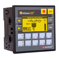
Kit Contents
Vision controller Programming cable + RS232 adapter
Symbol Meaning Description
D
anger The identified danger causes physical and property damage.
Warning The identified danger could cause physical and property damage.
Caution Caution Use caution.
Before using this product, the user must read and understand this document
All examples and diagrams are intended to aid understanding, and do not guarantee operation
Unitronics accepts no responsibility for actual use of this product based on these examples
Please dispose of this product according to local and national standards and regulations
Only qualified service personnel should open this device or carry out repairs
Failure to comply with appropriate safety guidelines can cause severe injury or property damage
Do not attempt to use this device with parameters that exceed permissible levels
To avoid damaging the system, do not connect/disconnect the device when power is on
Environmental Considerations
Do not install in areas with: excessive or conductive dust, corrosive or flammable gas,
moisture or rain, excessive heat, regular impact shocks or excessive vibration, i
n
ac
cordance with the standards given in the product’s technical specification sheet
Ventilation: 10mm space required between controller’s top/bottom edges & enclosure walls
Do not place in water or let water leak onto the unit
Do not allow debris to fall inside the unit during installation
Install at maximum distance from high-voltage cables and power equipment