Chapter 5: Communications
21
CANbus Wiring Specifications
Table 2: CANbus Specifications
Power Requirements:
24VDC (±4%),
40mA max. per unit
Galvanic Isolation
between CANbus and
controller:
Yes
Max. Network Cable Length:
1 Mbit/s -
500 Kbit/s -
250 Kbit/s -
125 Kbit/s -
100 Kbit/s -
50 Kbit/s -
20 Kbit/s
25 m
100 m
250 m
500 m
500 m
1000 m
1000 m
Note: If you require cable lengths over
500 meters, contact technical support.
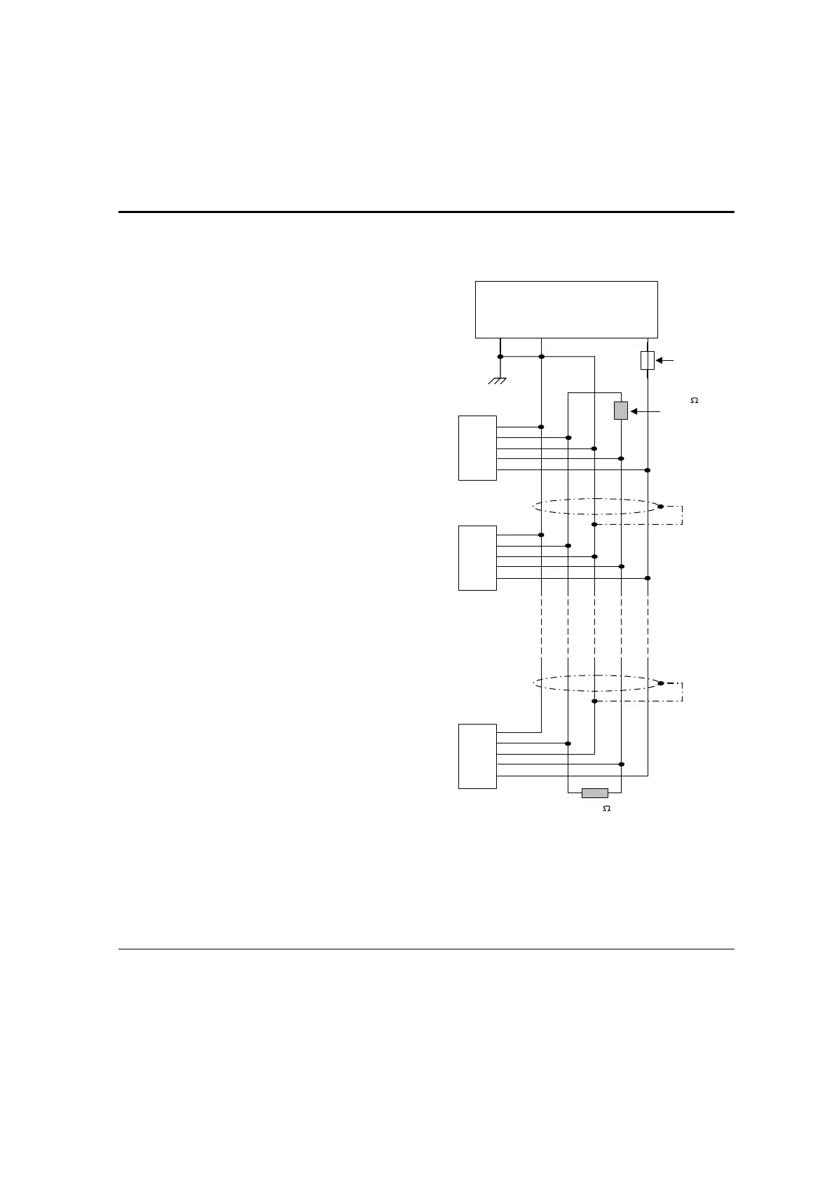
Table 3: Wiring Considerations
• Use twisted-pair cable. DeviceNet®
thick shielded twisted pair cable is
recommended.
• Network terminators: These are
supplied with the controller. Place
terminators at each end of the CANbus
network. Resistance must be set to 1%,
121Ω, 1/4W.
• Connect ground signal to the earth at
only one point, near the power supply.
• The network power supply need not be
at the end of the network
• Maximum number of controllers in a
network: 63
121
terminating
resistor
121
terminating
resistor
Circuit
protection
device
+
-
24V Power
Supply
-V
L
H
+V
PE
-V
L
H
+V
PE
-V
L
H
+V
PE
Figure 10. CANbus Wiring Diagram