ACCESSORIES
Section 8-13
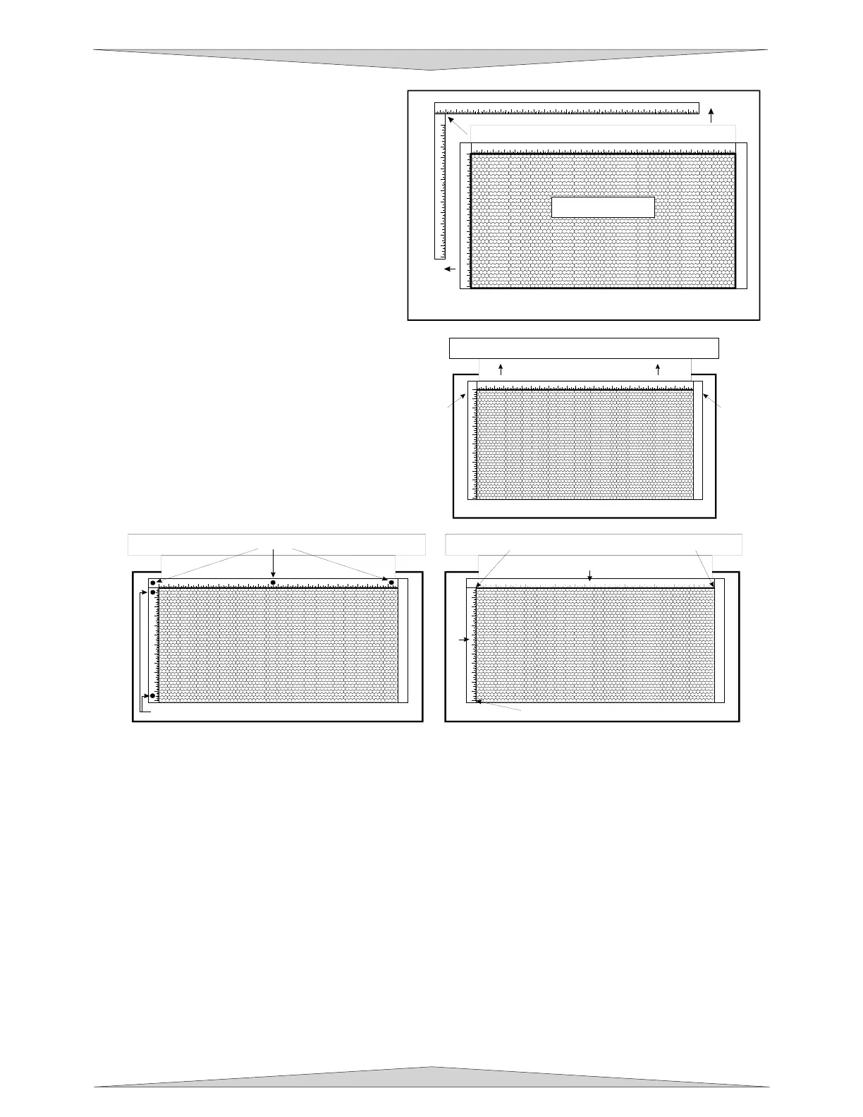
5. Open the front door of the laser system
and carefully slide the cutting table into
the laser system so that its body is
squarely pushed up against the engraving
table rulers on the top and the side of the
table. The rulers of the cutting table
should now overlap the rulers on the
engraving table.
6. Slide the adjustable manifold squarely up
against the exhaust plenum and tighten
the four (4) screws on the side of the
cutting table. Be careful not to move the
cutting table while tightening the screws.
The objective is to have the cutting table fit
snugly up against the rulers of the
engraving table and the adjustable
manifold fit tightly against the exhaust
plenum.
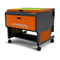
7. We now need to adjust the rulers of the
cutting table so that they match the
engraving field of the laser system. Using
the focus tool method (Section 9-17),
adjust the Z Axis and focus directly onto
the surface of the honeycomb.
8. Loosen slightly, but do not remove, the
five (5) screws that hold down the rulers.
9. Activate the red diode pointer by opening the top door. Position the focus carriage at (0,0). With the
red diode pointer still ON, slide the X-axis ruler so that its zero (0) point lines up with the red diode
pointer and tighten down the left side screw.
10. Now position the red diode pointer at the (32,0) position for th
e PLS6.75 and PLS6.150D series
machi
nes or (24,0) position for the PLS3.
75 and PLS4.75 series machine. Adjust the right side of the
X-axis rul
er until it is lined up with the diode. Tighten down the right side screw of the X-axis ruler.
Now tighten down the middle screw.
11. Line up the right edge of the Y-axis ruler with the zero (0) line of the X-axis ruler and tighten down the
top screw of the Y-axis ruler.
12. Finally, position the red diode pointer at the (0,18) position for th
e PLS6.75 and PLS6.150D series
machi
ne or the (0,12) position for the PL
S3.75 and PLS4.75 series machine. Align the bottom of the
Y-axis
ruler with the red diode pointer and tighten down the bottom screw of the Y-axis ruler. The
cutting table is now installed but lens calibration is needed.
1
2 3 4 5 6 7 8 9 10 11 12 13 14 15 16 17 18 19 20 21 22 23 24
1
2
3
4
5
6
7
8
9
10
11
12
1
2 3 4 5 6 7 8 9 101112131415161718192021222324
1
2
3
4
5
6
7
8
9
10
11
12
ENGRAVING TABLE
CUTTING TABLE
ADJUSTABLE MANIFOLD
1
23456789101112131415161718192021222324
1
2
3
4
5
6
7
8
9
10
11
12
ADJUSTABLE MANIFOLD
EXHAUST PLENUM
SCREWSSCREWS
1
2 3 4 5 6 7 8 9 10 11 12 13 14 15 16 17 18 19 20 21 22 23
1
2
3
4
5
6
7
8
9
10
11
12
1) POSITION DIODE HERE 2) THEN HERE
3) AND FINALLY HERE
X-AXIS RULER
Y-AXIS RULER
1
23456789101112131415161718192021222324
1
2
3
4
5
6
7
8
9
10
11
12
SCREWS
SCREWS