EasyManuals Logo

Universal Robots CB Series Installation Guide

Universal Robots CB Series
40 pages
To Next Page IconTo Next Page
To Previous Page IconTo Previous Page
Page #7 background image
1.Introduction
1.1. About this Document
This guide describes how to install an UniversalRobots OEMControlBox with the following
UniversalRobots robot arm sizes: UR3e, UR5e, UR10e, UR16e, UR20 and UR30.
Installation for both the AC variant and the DC variant are described.
NOTICE
UniversalRobots disclaims any liability, even if all guidelines in this document are
followed.
1.2. What the Box Contains
The box contains the following items:
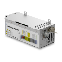
The OEM Control Box
This document
WAGO 831 four-pole female connector
Cable strain relief bracket
1.3. Company Details
UniversalRobotsA/S
Energivej 25, 5260 Odense S, Denmark
+45 89 93 89 89
https://www.universal-robots.com
Installation Guide OEM Control Box
Copyright © 2019–2024 by UniversalRobotsA/S. All rights reserved.

Other manuals for Universal Robots CB Series

Questions and Answers:

Universal Robots CB Series Specifications

General IconGeneral
Power Supply100-240 VAC, 50-60 Hz
IP RatingIP54
ProgrammingPolyscope graphical user interface
Payload Capacity3 kg, 5 kg, 10 kg
Reach500 mm, 850 mm, 1300 mm
Weight11 kg (CB3), 18.4 kg (CB3.1), 28.9 kg (CB3.1), 33.5 kg (e-Series)
Operating Temperature0°C to 50°C
Communication InterfacesEthernet/IP, Modbus TCP, PROFINET
Safety StandardsEN ISO 13849-1, EN ISO 10218-1
Degrees of Freedom6 rotating joints

Related product manuals