EasyManua.ls Logo

Universal Robots OEM Control Box User Manual

Universal Robots OEM Control Box
27 pages
To Next Page IconTo Next Page
Page #1 background imageLoading...
Page #1 background image
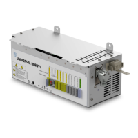
OEM Control Box
Installation Guide
Compatible robots: UR3e, UR5e, UR10e
Original instructions (en)

Questions and Answers:

Universal Robots OEM Control Box Specifications

General IconGeneral
Input Voltage100-240 VAC
Operating Temperature0-50°C
Ethernet Ports2
Digital inputs16
Digital outputs16
Analog inputs2
Analog outputs2
Weight12 kg
IP RatingIP20
Storage Temperature-25-70°C
Communication InterfaceEthernet
Dimensions475 x 423 x 268 mm
Supply Voltage24 VDC
SafetyCategory 3 PLd
Relative Humidity5-95% non-condensing

Summary

1. Introduction

1.1. About this Document

This document describes how to install the OEM Control Box.

1.2. What Does the Box Contain

Lists the items included with the OEM Control Box.

1.3. Company Details

Provides contact information for Universal Robots A/S.

2. Safety

2.1. Safety Message Types

Explains the different types of safety messages used in this document.

2.2. General Safety Precautions

Lists essential safety precautions for installing and operating the OEM Control Box.

3. Electrical Installation: AC Mains

3.1. Required Items

Lists the necessary items for connecting wires to the AC mains connector.

3.2. How to Connect Wires to the Connector

Details the procedure for connecting wires to the connector using locking levers.

3.3. Power Source Wiring

Explains the wiring scheme for connecting the OEM Control Box to the AC power source.

3.4. Robot Connection

Locates the Robot Arm connector and directs users to the manual for cable connection.

3.5. Circuit Breaker Installation

Describes the installation of a double pole circuit breaker for power input protection.

4. Electrical Installation: DC Source

4.1. Required Items

Lists the necessary items for connecting wires to the DC source connector.

4.2. How to Connect Wires to the Connector

Details the procedure for connecting wires to the connector using locking levers.

4.3. Power Source Wiring

Explains the wiring scheme for connecting the OEM Control Box to the DC power source.

4.3.1. Soft Start Circuit

Explains the need for a soft start circuit when using a DC source to manage inrush current.

4.4. Robot Connection

Locates the Robot Arm connector and directs users to the manual for cable connection.

4.5. Circuit Breaker Installation

Describes the installation of a double pole circuit breaker for power input protection.

5. Mechanical Installation

5.1. Working Environment Guidelines

Provides guidelines for ensuring reliable operation of the OEM Control Box.

5.2. Mounting the OEM Control Box

Details how to mount the OEM Control Box using the four mounting brackets.

5.2.1. Grounding

Explains that the casing is connected to the ground pin and conductive surfaces must be grounded.

6. Connecting External Devices

6.1. Control Ports

Describes the ports available on the bottom of the OEM Control Box for connecting devices.

6.1.1. Connecting a Mouse, Keyboard, or Monitor

Explains how to connect peripherals via USB and a monitor via Mini DisplayPort.

6.1.2. Teach Pendant, Remote Control, Local Control

Details connecting the Teach Pendant and enabling Remote/Local Control.

6.2. Setting up Remote ON/OFF Control and Emergency Stop

Describes installing remote ON/OFF control and an emergency stop pushbutton using I/O ports.

6.2.1. Connecting the ON/OFF Control

Shows how to connect a remote ON/OFF control using the provided diagram and table.

6.2.2. Connecting Remote Emergency Stop

Illustrates the minimum required installation for an external Emergency Stop (E-stop).

7. Specifications

7.1. Electrical Specifications

Lists input voltage, frequency, fuses, and power consumption for AC and DC OEM Control Boxes.

7.2. Control Unit Heat Dissipation

Provides heat dissipation values for different robot models (UR3e, UR5e, UR10e).

7.3. Dimensions

Lists the physical dimensions and weights of the OEM Control Box.

7.4. Dimensional Drawings [mm]

Presents detailed dimensional drawings of the OEM Control Box with measurements.

8. Troubleshooting

8.1. OEM Control Box AC

Lists common symptoms and possible solutions for AC powered OEM Control Box issues.

8.2. OEM Control Box DC

Lists common symptoms and possible solutions for DC powered OEM Control Box issues.

9. Certificates

9.1. Shipping Materials

States compliance with ISPM-15 requirements for wood packaging materials.

9.2. Certification of Quality

Describes Universal Robots' continuous internal testing and quality assurance processes.

9.3. Declarations According to EU directives

Lists EU directives (Machinery, Low-voltage, EMC, RoHS, WEEE) relevant to the robots.

9.4. EU Declaration of Incorporation

Provides the EU Declaration of Incorporation for the partially-completed machine.

9.5. China RoHS

Presents the Product Declaration Table for Toxic or Hazardous Substances for China RoHS.

Related product manuals