NOTICE
Connecting wires to poles without labels may interfere with the operation of the
robot.
l Do not connect wires to poles without labels.
3.4. Robot Connection
The Robot Arm connector is next to the power supply connector. For details on connecting the
Robot Arm cable, refer to the robot user manual.
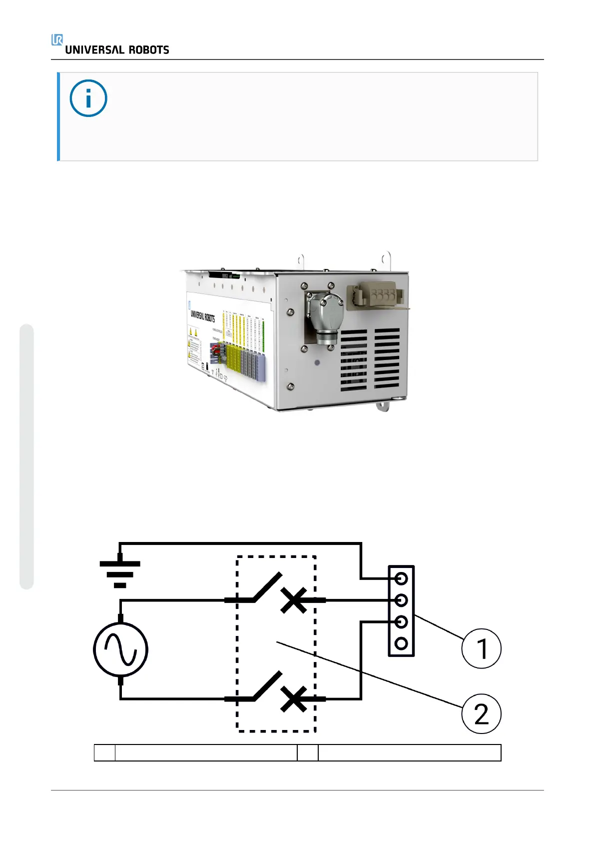
3.5. Circuit Breaker Installation
Use a double pole circuit breaker to protect the power input connector, as it can also be used as
a switch. If a fuse is used, then a two-pole switch must be installed between the fuse and power
input connector.
The following illustration shows the circuit breaker wiring scheme.
1 Power input 2 Circuit breaker
OEM Control Box 6 Installation Guide
3. Electrical Installation: AC Mains
Copyright © 2019 by UniversalRobotsA/S. All rights reserved.