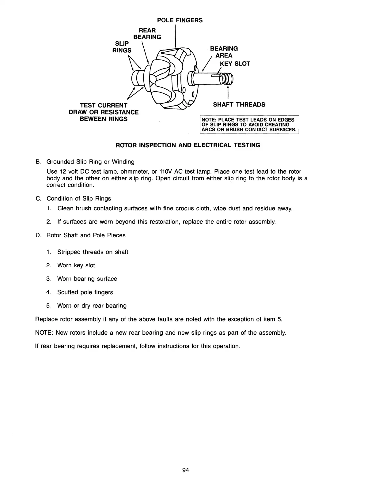
POLE FINGERS
REAR I
BEARING
SLIP
\
RING~
TEST CURRENT
DRAW
OR
RESISTANCE
BEWEEN RINGS
BEARING
AREA
/ KEY
SLOT
SHAFT THREADS
NOTE: PLACE TEST LEADS ON EDGES
OF SLIP RINGS
TO
AVOID CREATING
ARCS ON BRUSH
CONTACT SURFACES.
ROTOR INSPECTION AND ELECTRICAL TESTING
B.
Grounded Slip Ring or Winding
Use
12
volt DC test lamp, ohmmeter, or
110V
AC test lamp. Place one test lead to the rotor
body and the other on either
slip ring. Open circuit from either slip ring to the rotor body is a
correct condition.
C.
Condition of Slip Rings
1.
Clean brush contacting surfaces with fine crocus cloth, wipe dust and residue
away.
2.
If surfaces are worn beyond this restoration, replace the entire rotor assembly.
D.
Rotor Shaft and Pole Pieces
1.
Stripped threads on shaft
2. Worn key slot
3.
Worn bearing surface
4.
Scuffed pole fingers
5.
Worn or dry rear bearing
Replace rotor assembly if any of the above faults are noted with the exception of item
5.
NOTE: New rotors include a new rear bearing and new slip rings as part of the assembly.
If
rear bearing requires replacement, follow instructions for this operation.
94