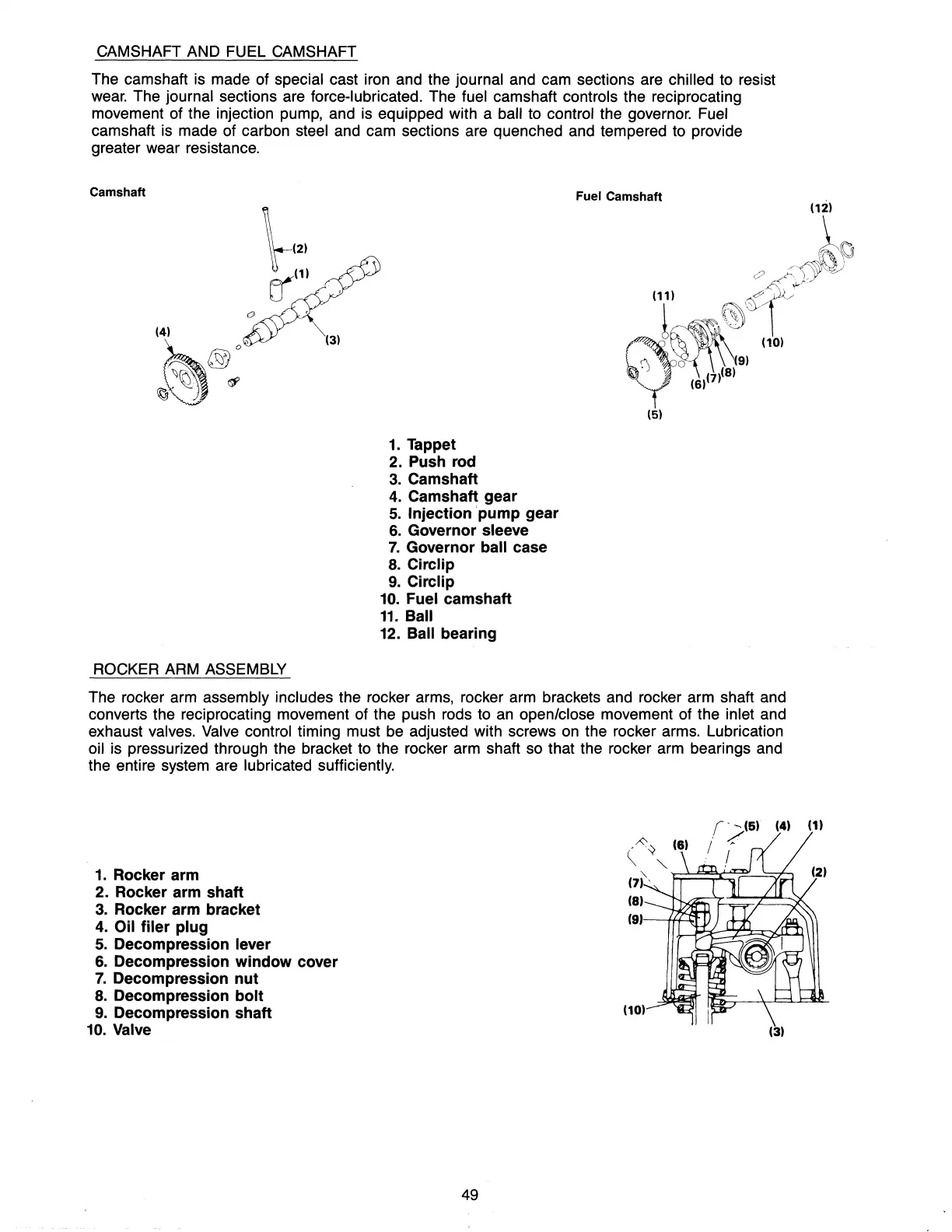
CAMSHAFT AND FUEL CAMSHAFT
The camshaft is made of special cast iron and the journal and cam sections are chilled to resist
wear. The journal sections are force-lubricated. The fuel camshaft controls the reciprocating
movement of the injection pump, and is equipped with a
ball to control the governor. Fuel
camshaft is made of carbon steel and cam sections are quenched and tempered to provide
greater wear resistance.
Camshaft
Fuel Camshaft
1.
Tappet
2. Push rod
3.
Camshaft
4.
Camshaft gear
5.
Injection 'pump gear
6.
Governor sleeve
7.
Governor ball case
8.
Circlip
9.
Circlip
10.
Fuel camshaft
11.
Ball
12. Ball bearing
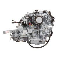
ROCKER ARM ASSEMBLY
The rocker arm assembly includes the rocker arms, rocker arm brackets and rocker arm shaft and
converts the reciprocating movement of the push rods to
an
open/close movement of the inlet and
exhaust valves.
Valve control timing must be adjusted with screws on the rocker arms. Lubrication
oil is pressurized through the bracket to the rocker arm shaft so that the rocker arm bearings and
the entire system are lubricated sufficiently.
1.
Rocker arm
2. Rocker arm shaft
3.
Rocker arm bracket
4.
Oil
filer
plug
5.
Decompression lever
6.
Decompression
window
cover
7.
Decompression
nut
8.
Decompression
bolt
9.
Decompression shaft
10.
Valve
49
,~~
(8)
~
"-
(4) (1)
(7)"
'F;:!===~~~~
(8)
(9)---fH.40T
(3)