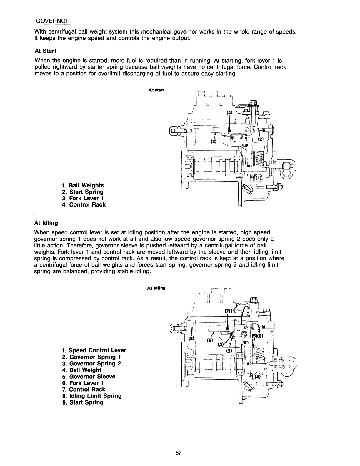
GOVERNOR
With centrifugal ball weight system this mechanical governor works
in
the whole range of speeds.
It keeps the engine speed
and
controls the engine output.
At
Start
When the engine
is
started, more fuel is required than
in
running.
At
starting, fork lever 1
is
pulled rightward
by
starter spring because ball weights
have
no
centrifugal
force.
Control rack
moves
to
a position for overlimit discharging of fuel
to
assure easy starting.
At
start
1.
Ball Weights
2.
Start Spring
3.
Fork Lever 1
4.
Control Rack
At
Idling
When speed control lever
is
set
at
idling position after the engine is started, high speed
governor spring 1 does not work
at
all and also low speed governor spring 2 does only a
little action. Therefore, governor sleeve
is
pushed leftward by a centrifugal force of ball
weights.
Fork
lever 1
and
control rack are moved leftward
by
the sleeve and then idling limit
spring
is
compressed
by
control rack.
As
a result, the control rack
is
kept
at
a position where
a
centrifugal force of ball weights and forces start spring, governor spring 2 and idling limit
spring
are
balanced, providing stable idling.
At
idling
1.
Speed Control Lever
2.
Governor Spring 1
3.
Governor Spring 2
4.
Ball Weight
5.
Governor Sleeve
6.
Fork Lever 1
7.
Control Rack
8.
Idling
Limit
Spring
9.
Start Spring
67