MSC-400 Reference Manual
Rev 4
17
IR OR RS232 PROGRAMMABLE OUTPUTS (Ports 7-12) – RS232
NOTE - There are two versions of the RS232 cable. The RS232M has a male DB9 connector and
the RS232F has a female DB9 connector. Be sure to verify the proper cable configuration by
visually inspecting the RS232 terminal on the device to be controlled. Some devices will use other
types of connectors such as RJ45 and mini jacks. Custom cables can be made using the pin-out
for the MSC-400 jacks as shown in G Typical System. Please refer to the device owner’s manual
for the pin-out of RS232 Terminals that are not DB9 connectors.
1. Connect the 3.5 MONO 4-CIRCUIT MINI PLUG end of a URC RS232M/F to the appropriate IR OR
RS232 PROGRAMMABLE OUTPUT JACK.
TIP - This step is critical in that once cond and programmed, the MSC-400 will only send a
specific device’s RS232 commands to that device via the assigned RS232 Port. If an RS232
cable is not connected to the proper RS232 port, the MSC-400 will be sending commands to
the wrong device. Keep written notes of which device’s RS232 cables are connected to which
RS232 ports and label each RS232 cable at the plug end for type, brand and model as well as
the RS232 Port number.
2. Connect the DB9 CONNECTOR to the device RS232 TERMINAL. Tighten the thumb screws to
secure the connection.
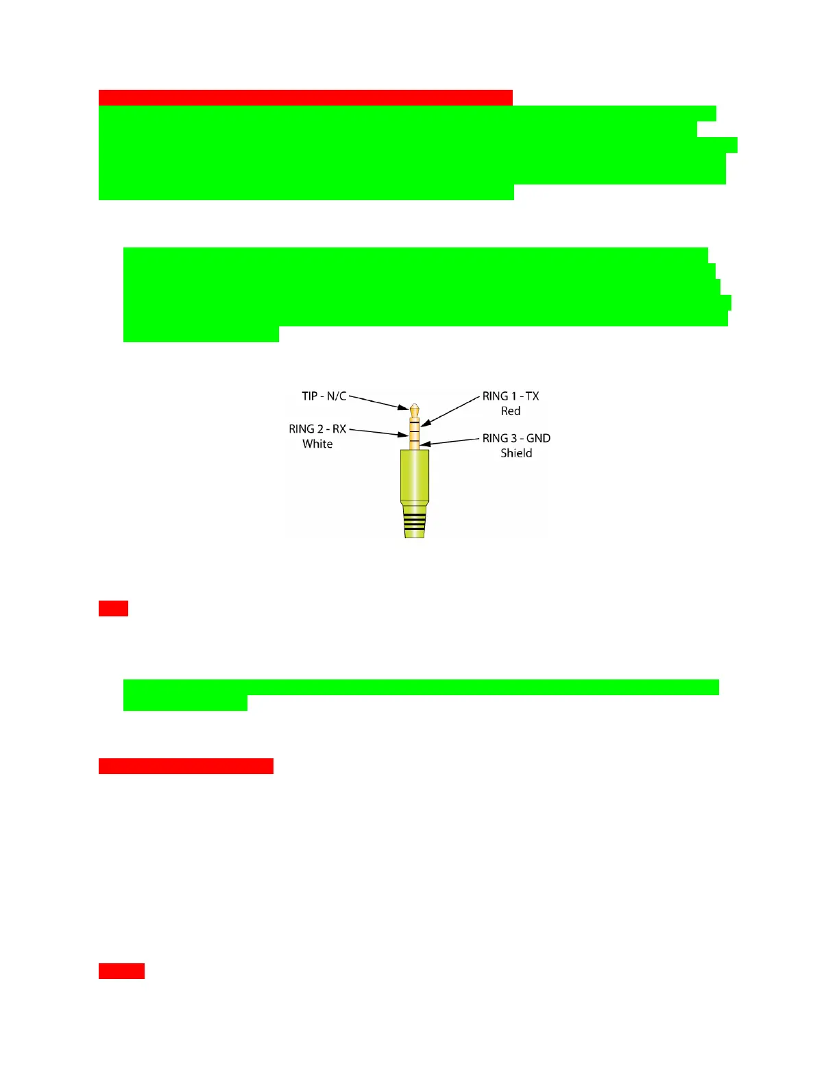
8 RS232 3.5 Mono Mini Plug Pin-Out
IR In
1. Using appropriate 3-conductor 24-14AWG wire, connect the +12, SIGNAL AND GROUND from an IR
REPEATER SYSTEM to one of the included three-pin plug-in connectors for IR control of Connected
Devices. The MSC-400 will output IR signals input to this terminal to ALL IR PORTS. (No routing for
selective control.)
NOTE - IF THE IR REPEATER SYSTEM HAS ITS OWN POWER SUPPLY, DO NOT MAKE THE
12V CONNECTION.
2. Confirm polarity from the IR system prior to making connections. Be sure there are no loose strands
that can cause shorts.
RF In (RFX-250 RF Sensor)
1. Using the included 10’ 4-CIRCUIT MINI-MINI CABLE, connect the RF OUT on the RFX-250 RF
SENSOR to the RF IN on the MSC-400 REAR PANEL as shown in 7 Typical System. The RFX-250
can also be connected via three conductor wire, using one of the included 3-pin plug-in connectors.
2. If connecting multiple RFX-250’s, the 3.5 monoJACK and PLUG-IN TERMINAL are PARALLEL, so
both can be used. When connecting MULTIPLE RF SENSORS with the plug-in connector, CHECK
POLARITY from each RFX-250 prior to making connections. Be sure there are no loose wire strands
that can cause shorts.
3. Once the system has been powered up, the RFX-250 POWER LED should illuminate RED.
4. Be sure to TEST THE RFX-250 location for RF INTERFERENCE as described in Section: RFX-250
INSTALLATION.
5. WIRE: CAT 5 or two conductor shielded 18 gauge ; MAX WIRE LENGTH: 200’
RF Out