MSC-400 Reference Manual
Rev 4
9
RFX-250 RF SENSOR
The RFX-250 receives narrow-band radio signals from compatible narrow-band RF remote controls and
relays them via a connecting cable to the MSC-400. The narrow-band RF technology and advanced
protocol used in the RFX-250 improves reliability and extends receiving range. The compact size and
detached design enables the RFX-250 to be placed in discrete locations, away from RF interference
generated by system components (when necessary).
RFX-250 RF Sensor Features
4 RFX-250 RF Sensor
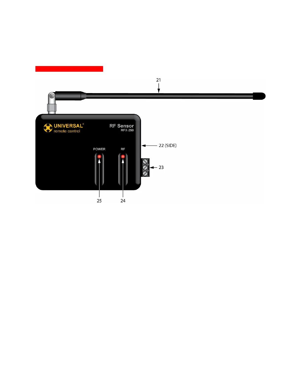
21. Antenna – One flexible antenna, receives RF signals from MSC compatible remotes. The antenna
can be rotated and angled to optimum reception position.
22. RF Out (Mini Jack) – One three-circuit 3.5 mono mini jack provides power to the RFX-250 and sends
understood RF commands to the MSC-400. This jack can be connected to either of the RF IN’s on
the MSC-400 rear panel. POLARITY: TIP=+5VDC; RING=data; SLEEVE=GND.
23. RF Out (Plug-In) – One three-pin plug-in connector terminal provides power to the RFX-250 and
sends understood RF commands to the MSC-400. This terminal can be connected to either RF IN on
the MSC-400 rear panel.
24. RF LED – One red LED flashes when the RFX-250 is receiving RF signals from a MSC compatible
remote. This LED will also turn on in a range from low glow flicker to full on constant, when RF noise
is present. This is useful in troubleshooting for positioning the RF Sensor in a location clear of RF
interference (LED off).
25. Power LED – One red LED illuminates to indicate the RFX is powered from the MSC-400.