Page 9.1
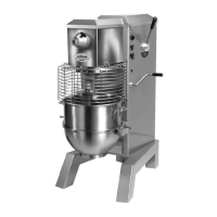
HOUSING ASSEMBLY
(Figure 15)
The remaining parts which have not been discussed pertain to electrical components and the mixer
housing. Figures 15, 16A, 16B, 16C, 16D, 16E, and 16F should provide adequate guidance for the
disassembly and reassembly of these parts.
MIXER HOUSING ASSEMBLY
FIGURE 15
ILLUS. No. PART No. DESCRIPTION QTY.
1 1064550A Safety Ring Set (SRM60) 1
1080051A Safety Ring Set (SRM80) 1
2 1064554 Fixed Slide Cover (SRM60) 1
1080055 Fixed Slide Cover (SRM80) 1
3 1012441A Safety Ring Bracket Kit 1
4 1064412A Top Cover Assembly (SRM60) 1
1080023A Top Cover Assembly (SRM80) 1
5 1064419A Rear Access Panel Assembly 1
6 1024411A Switch Assembly 1
7 7100027A Timer Assembly 1
8 7100101 Start Button 1
9 7100102 Stop Button 1
The following are not shown:
10 7100009 Contactor / Starter, 208-240V, 60HZ, 1PH 1
7100006 Contactor / Starter, 208-240V, 60HZ, 3PH 1
7100008 Contactor / Starter, 220-240V, 50HZ, 1PH 1
7100007 Contactor / Starter, 380V, 50HZ, 3PH / 460V, 60HZ, 3PH 1
7100114 Contactor / Starter, 200V, 50-60HZ, 3PH 1