56 “Translation of the original instruction”
WaWa
13. Remove the positioning fasteners on the
arm length pin (label # 3).
CAUTION: Do not remove the outer opening
ring.
14.Use a soft metal punch to remove the pin
and place it aside.
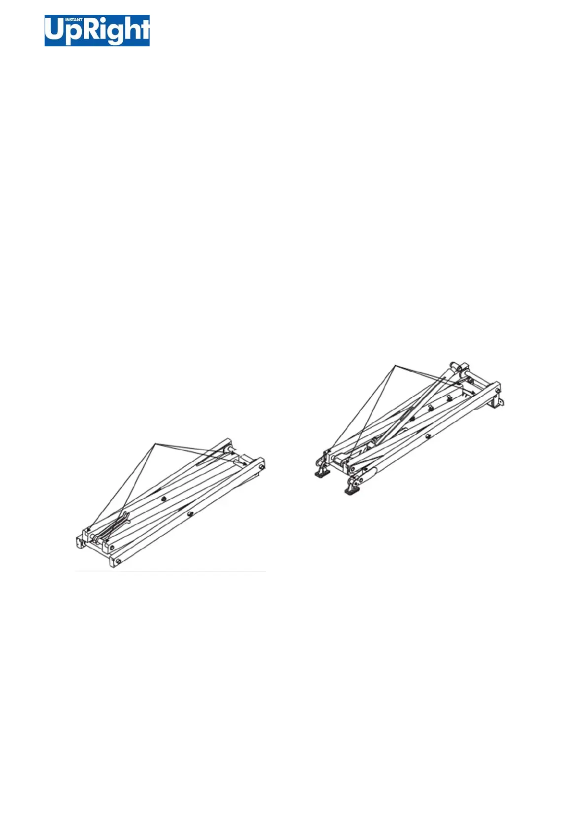
15.Carefully lift the connecting rod assembly
away from the machine and place it on the
device structure that can support it.
16.Use the air lifting device to connect the 4
hook chain to the end of the (# 13) middle
shearing arm 3. Tension the chain, but do not
apply lifting pressure.
Warning! The risk of injury. When removing the
connecting rod assembly from the machine, if
the support is improper, the connecting rod
assembly will lose balance and fall.
17.Remove the positioning fasteners on the arm
length pin (label # 3).
CAUTION: Do not remove the outer opening
ring.
18.Use a soft metal punch to remove the pin
and place it aside.
19.Carefully lift the connecting rod assembly
away from the machine and place it on the
device structure that can support it.
20.Mark and disconnect the harness on the lifting
cylinder block.
21.Mark and disconnect the hydraulic hoses on the
lifting hydraulic cylinder. Plug the hose and cover the
joint with the cover.
Warning! The risk of injury. When removing
the connecting rod assembly from the machine, if the
support is improper, the connecting rod assembly will
lose balance and fall.
22.Remove the hose clamp and hose from the trim arm
4.
23.Connect the 4 hook chain to the end of the middle
arm 4 (# 6) using an air lift device. Tension the chain,
but do not apply lifting pressure.
Warning! The risk of injury. When removing the
connecting rod assembly from the machine, if the
support is improper, the connecting rod assembly will
lose balance and fall.
24.Remove the positioning fasteners on the base arm
(label # 7).
CAUTION: Do not remove the outer opening ring.
25.Use a soft metal punch to remove the pin and place
it aside.
26.Move the link mechanism toward the non-steering
end of the machine until the chassis slider leaves the
slide.
27.Carefully lift the connecting rod assembly away from
the machine and place it on the device structure that
can support it.