62 “Translation of the original instruction”
4-3
5.3.3Method to Remove the
Steering Wheel Seat Assembly
1.Lock the non-steering wheel and place a jack in the
center of the drive chassis of the machine's steering
end.
2.Loosen the wheel lugs. Do not remove them.
3.Lifting machine about 5CM. Place the pad under the
chassis as support.
Warning! The risk of injury. If the support is improper,
the chassis may fall.
4.Remove the wheel lugs. Remove the tire and wheel
assembly.
5.Use a lifting device to support and secure the steering
wheel assembly.
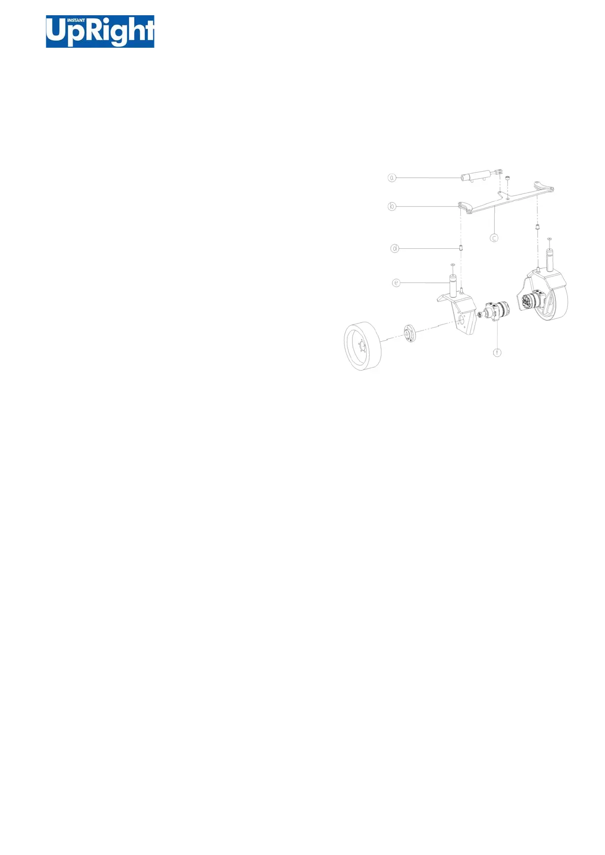
Right Steering Seat
1.Remove the positioning fasteners on the wheel
seat arm b.
a. 140w Steering cylinder
b. Wheel seat arm
c. Steering connection plate
d. Steering seat plastic cover
e. Wheel seat right welding
f. Hydraulic motor
2.Remove the wheel seat arm.
3.Remove the right steering wheel assembly e from
the machine.
Caution! The risk of injury. When the steering
wheel assembly is removed from the machine, the
steering wheel assembly may fall out of balance if it
is not properly supported and is not secured with a
suitable lifting device.
4.Repeat the above steps to remove the left
steering wheel assembly.