4
Transporting Work Platform
By Forklift
NOTE: Forklifting is for transporting only.
See specifications for weight of work
platform and be certain that forklift is of
adequate capacity to lift platform.
Forklift from side or rear using fork pockets pro-
vided (Figure 5).
By Crane
1. Secure straps to chassis lifting/tie down points
only (Figure 5).
By Truck
1. Maneuver the work platform into transport
position and chock wheels.
2. Secure the work platform to the transport
vehicle with chains or straps of adequate load
capacity attached to the chassis lifting/tie down
points (Figure 5).
Overtightening of chains or straps attached
to tie down lugs may result in damage to
work platform.
After Use Each Day
1. Ensure that the platform is fully lowered.
2. Park the machine on level ground, preferably
under cover, secure against vandals, children
or unauthorized operation.
3. Turn the Key Switch to OFF and remove the
key to prevent unauthorized operation.
Parking Brake Release (Figure 4)
Perform the following only when the machine will not
operate under its own power and it is necessary to
move the machine or when towing the machine up a
grade or winching onto a trailer to transport.
The Brake Adjustment/Release Bolt is located at
the rear of the machine between the rear wheels.
1. To release the brakes loosen the jam nut and
bolt until the brakes disengage from the tires.
2. The machine will now roll when pushed or
pulled.
3. To re-engage the brakes tighten the bolt until
the brakes have fully engaged the tires, secure
the bolt with the locknut . Be sure to verify that
the brakes have fully engaged the rear tires
before the machine is operated.
Never operate work platform with the
Parking Brakes released. Serious injury or
damage could result.
Never tow faster than 1 ft./sec. (.3m/sec.).
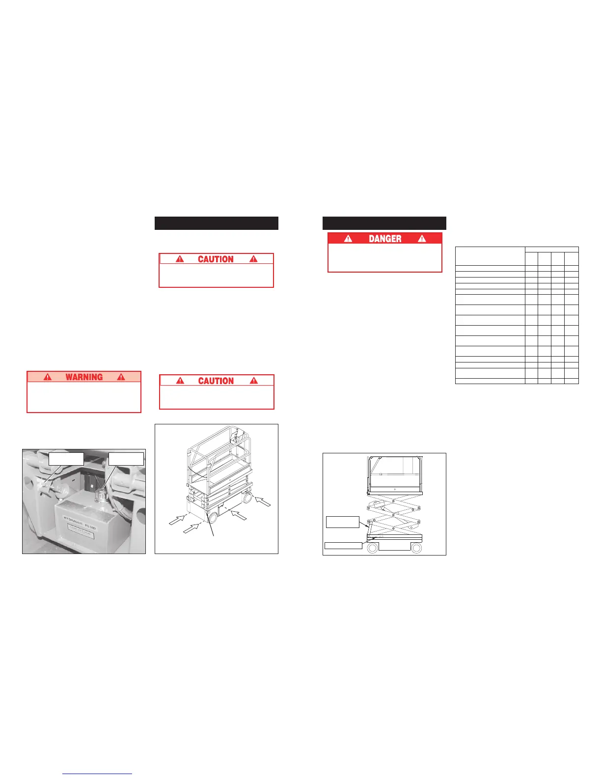
Figure 5: Transporting Work Platform
Typical Tie Down/
Lifting Lug
Forklift
Forklift
Figure 4: Chassis Rear View
Brake Release
Bolt
Hydraulic Tank
Cap
5
Figure 6: Blocking Elevating Assembly
Routine Service
Use the following table as a guide for routine
maintenance, refer to the Service Manual for
complete service instructions.
SERVICE OPERATION INTERVAL
Monthly
6 Months
2 Years
Daily or or or
50 Hrs. 250 Hrs.
1000 Hrs.
Clean entire work platform X
Check battery fluid level X
Charge batteries X
Check tires for damage X
Check hydraulic fluid level X
Check for peeling, faded or X
missing labels & replace
Check deck and guardrail X
fasteners for proper torque
Inspect elevating assembly X
for bends or cracks
Check for & repair collision X
damage
Check emergency lowering X
valve operation
Check electric motor X
brushes
Check pivot pin retaining rings X
Change hydraulic filter X
Check all fasteners for X
proper torque
Change hydraulic fluid X
Scissor Brace
Installed
Stowed Position
Maintenance
Never perform service on the work platform
in the Elevating Assembly area while the
platform is elevated without first blocking
the Elevating Assembly.
Blocking Elevating Assembly (Figure 6)
Installation
1. Park the work platform on firm level ground.
2. Verify Platform Emergency Stop Switch is ON.
3. Turn Chassis Key Switch to CHASSIS.
4. Position Chassis Lift Switch to UP and elevate
platform approximately 7 Ft. (2.1 m).
5. Rotate Scissor Brace to a verticle position.
6. Lower Platform until end of Scissor Arm Weld-
ment rests on Brace.
Storage
1. Slowly raise Platform from the Chassis Controls,
while holding Brace, until the end of the Scissor
Arm Weldment clears the Scissor Brace.
2. Rotate Scissor Brace forward to rest on Chassis.
 Loading...


