Schematics
UL-25/32/40/48 Portable Personnel Lifts6-2
Section
REFERENCE
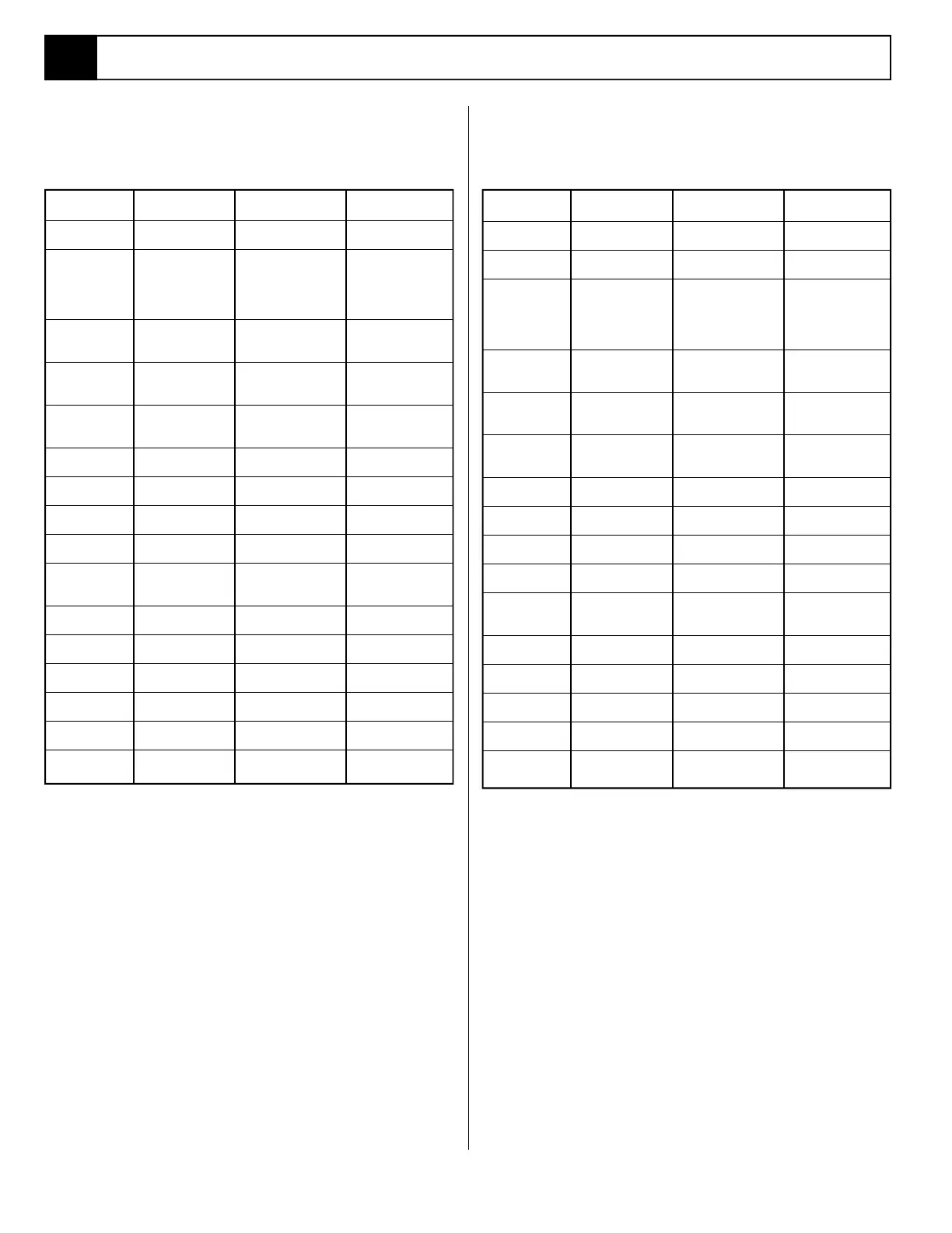
DESIGNATION NAME FUNCTION LOCATION
BR Bridge Rectifier Converts AC to DC In Control Box.
for control circuit.
C1-4 Relay Contacts Completes ground In Control Box.
Norm. Open for circuit to motor
R1-4. and Lift Valve
when R1-4 are
energized.
L1-4 Indicator Light Lights when Outrigger On chassis next to
Interlock Switches Outrigger socket.
are closed.
M1 Electric Motor Supplies power to Upper portion of
drive hydraulic Power Unit.
pump.
R1-4 Relay Coil When energized In Control Box.
closes relay contacts
1-4.
R5 Motor Contactor Switches power to In Control Box.
Electric Motor.
S1 Switch, Chassis Control circuit In Control Box.
Emergency Stop shut off.
S2 Switch, Key Provides power to In Control Box.
upper controls.
S3 Switch, Platform Control Circuit In Control Box.
Emegency Stop shut off.
S4 Switch. Power Supplies power to Center button of
On either Up or Down platform controls.
Switch.
S5 Switch, Lift Supplies power to Upper button of
up circuit. platform controls.
S6 Switch, Lower Supplies power to Lower button of
down circuit. platform controls.
S7-10 Switch, Outrigger Supplies power to In Outrigger Sockets.
Interlock L1-L4 and R1-R4.
SOL1 Solenoid, Lower Opens down valve. Power Unit front.
(coil)
SOL2 Solenoid, Lift Opens Up Valve. Power Unit left
(coil) hand side.
T1 Transformer Steps down AC Inside electrical
voltage. Control Box.
6.1 Electrical Schematics
REFERENCE
DESIGNATION NAME FUNCTION LOCATION
BAT Battery Supplies current to In Power Module.
circuit.
CH Charger Maintains Charge In Power Module.
level in Battery.
C1-4 Relay Contacts Completes ground In Control Box.
Norm. Open for circuit to motor
R1-4. and Lift Valve
when R1-4 are
energized.
L1-4 Indicator Light Lights when Outrigger On chassis next to
Interlock Switches Outrigger socket.
are closed.
M1 Electric Motor Supplies power to Upper portion of
drive hydraulic Power Unit.
pump.
R1-4 Relay Coil When energized In Control Box.
closes relay contacts
1-4.
R5 Relay, Motor Supplies power to Lower Power Module.
Motor.
S1 Switch, Chassis Control circuit In Control Box.
Emergency Stop shut off.
S2 Switch, Key Provides power to In Control Box.
upper controls.
S3 Switch, Platform Control Circuit In Control Box.
Emegency Stop shut off.
S4 Switch. Power Supplies power to Center button of
On either Up or Down platform controls.
Switch.
S5 Switch, Lift Supplies power to Upper button of
up circuit. platform controls.
S6 Switch, Lower Supplies power to Lower button of
down circuit. platform controls.
S7-10 Switch, Outrigger Supplies power to In Outrigger Sockets.
Interlock L1-L4 and R1-R4.
SOL1 Solenoid, Lower Opens down valve. Power Unit front.
(coil)
SOL2 Solenoid, Lift Opens Up Valve. Power Unit left
(coil) hand side.
Table 6-1: Electrical Schematic Legend AC Table 6-2: Electrical Schematic Legend DC
6.1



 To Next Page