UL-25/32/40/48 Portable Personnel Lifts
Introduction & Specifications
Section
1-1
1.0 Introduction
PURPOSE OF EQUIPMENT
The UpRight Personnel Lift is a portable lift designed to
elevate personnel and light equipment to work above
the ground.
GENERAL DESCRIPTION
There are four basic UpRight Personnel Lift models: the
UL-25, UL-32, UL-40 and the UL-48.
All models consist of a Platform, Mast and Chassis.
The UL-32, UL-40, and UL-48 are equipped with a tilt
back mechanism to facilitate passage through a standard
80 inch doorway. This tilt back mechanism is optionally
available in a configuration adapted to fit the UL-25.
Platform
The platform is an aluminum structure supported by a
steel cage support attached to the mast. It has 43.5-inch
high "clamshell" upper and lower guardrail assembly
with gas spring assist for opening and closing, six (6) inch
toeboards and integrated midrail.
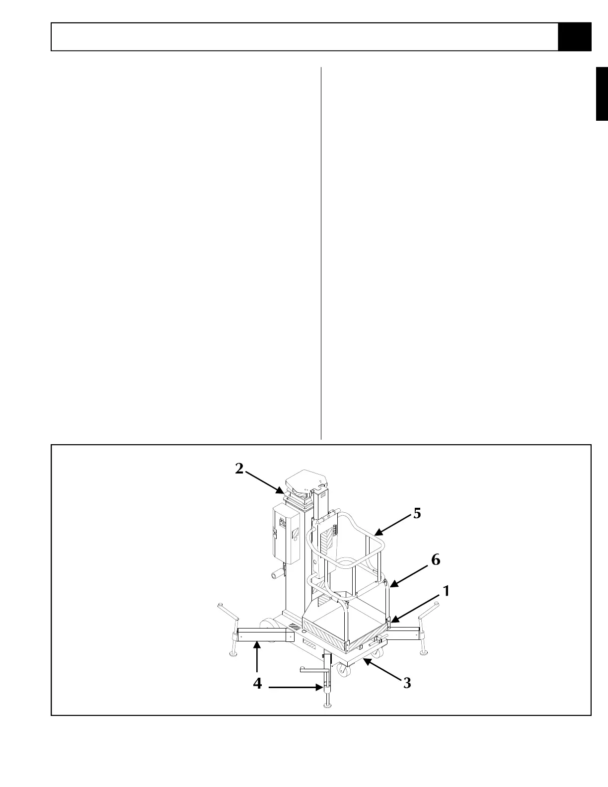
Figure 1-1: UL Portable Personnel Lift
Mast
The platform is raised and lowered by a seven stage
mast assembly that is driven by a single stage hydraulic
lift cylinder and a series of leaf chains. An AC or DC
electric motor powers a hydraulic pump which in turn
energizes the cylinder. Solenoid operated valves control
the raising and lowering of the Platform.
Chassis
The Chassis is a steel structure that consists of the first
stage of the Mast Assembly, control box, battery charger
(for DC Models), and AC or DC Motor, hydraulic pump
and reservoir, 12v battery (for DC Models), a tilt baCk
assembly (standard on 32', 40', and 48' machines,
optional on 25' machines), and four Outriggers. The
chassis is equipped with outrigger status lights which
indicate that outrigger interlock switches are closed
Operator Controls
Controls consist of a Lower Emergency Stop Switch,
Upper Emergency Stop Switch, Key Switch and three (3)
push button controls: Power On, Up, Down. The
Power On button must be pushed along with the Up or
Down button to operate the machine. An Emergency
Lowering Valve is located on the power unit at the base
of the machine.
1.0
1. Platform
2. Mast
3. Chassis
4. Outriggers
5. Upper Guardrail (Gate)
6. Lower Guardrail



 To Next Page