INTRODUCTION
WIRES
http://www.miwiurmet.com.pl e-mail:miwi@miwiurmet.com.pl
5
INTRODUCTION
Matibus SE is suitable for medium door phone and video door
phone installations. Matibus SE is ideal for making new systems
and modernizing old ones.
BASIC FEATURES OF THE MATIBUS SE
1. 2-wire installation for door phone system, regardless of the
number of users,
2. Secrecy of the conversations,
3. Maximum number of door phones (510),
4. The ability to create systems with the main and additional
entrances,
5. Built into the keyboard lock function code,
6. Built-in panel additional relay, for example to control automatic
gate,
7. General codes for opening the doors (64), may be individual
for each of the keyboards
8. 510 individual codes opening the door associated with
members codes,
9. The maximum number of keyboards 239,
10. House phones programming by the setting jumpers,
11. The possibility of parallel connection 2 house phones,
12. Signaling the open door,
13. The possibility to work with switchboard,
14. Additional service features such as measurement of the
current in the house phones line.
15. Possibility of connection analog call module using digitiser.
16. Call Module with Dallas key reader.
INSTALLATION PARAMETERS OF THE
SYSTEM MATIBUS
LOCATION DEVICES
All equipment should be installed in dry and ventilated places, it is
recommended that it is assembled in special boxes designed for
this purpose.
Equipment should be separated from the electrical, telephone and
antenna installations.
WIRES
A single terminal lets you connect maximum wire 1.5 mm
2
.
Important is protection against short circuits between adjacent
terminals.
All wires should be stapled together and properly labeled.
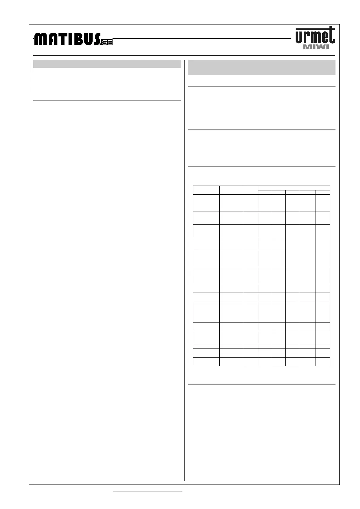
MAXIMUM DISTANCE AND WIRES CROSS-SECTIONS
Maximum distance in meter between devices depends on wires
cross-section, as shown below:
Distance [m]
Line
25 50 100 200 300
Power
supply
panel /
digitiser
12 V AC mm
2
0.5 0.5 1
(1)
-
(2)
-
(2)
Data line
panel /
digitiser
D mm
2
0.5 0.5 1 1.5
(2)
2.5
(2)
Audio line
panel /
digitiser
LG mm
2
0.5 0.5 1 1.5
(2)
2.5
(2)
Ground
panel /
digitiser
0L mm
2
0.5 0.5 1 1.5
(2)
2.5
(2)
Line
between
system
power units
D, LG, OL mm
2
0.5 0.5 1 1.5 2.5
Guard door
switchboard
– system
power unit
D, LG, OL mm
2
0.5 0.5 1 1.5 2.5
Electric lock
line
+CL mm
2
0.5 1 - - -
Electric lock
line
-CL mm
2
0.5 1 - - -
Digitiser-
Analog call
module
GR1..GR3
G1..G8
441, GL1,
GL2, AC1,
AC2
mm
2
0.5 1 1 1.5 1.5
Video
Ground Line
R1 mm
2
0.75 1.5 2.5 2.5
(3)
2.5
(3)
Video
power
supply line
R2 mm
2
0.5 1 2.5 -
(3)
-
(3)
Video signal A, B mm
2
0.35 0.35 0.35 0.35
(4)
-
Video signal V3, V5 mm
2
0.5 0.5 0.8 1 1.6
Ground 0L mm
2
0.5 0.75 1 1.5 2.5
Signaling
Line
LU1, LU2 mm
2
0.5 0.5 1 1.5 2.5
ELECTRICAL CONECTIONS
All the electrical connections must be made by the man with basic
knowledge of electrical engineering.
Power supply has to be turned off.
 Loading...