28 Remote Booster Power Supply Technical Reference Manual
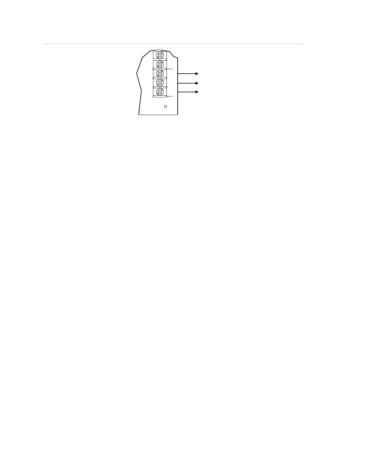
Figure 17: Common trouble relay wiring
NC
TROUBLE
COM NO
OUT
SEN
CO
TB2
(1)
(1) To booster trouble monitoring device
When using the sense circuit as common trouble relays, the BPS operates as
outlined in the following scenarios.
Scenario 1: Trouble on any non-AC power fault
Result:
• Sense 1 opens.
• An AC power failure closes the trouble contact at 20 seconds and activates
Sense 1 at three hours.
For a wiring example, see Figure 16 on page 27.
Scenario 2: Sense 1 activates all four NAC circuits
Result:
• Sense 1 opens.
• An AC power failure closes the trouble contact at 20 seconds and activates
Sense 1 at three hours.
For a wiring example, see Figure 19 on page 30.
Scenario 3: Sense 1 and Sense 2 are operating with multiple CC1 modules
Result:
• A fault on NAC 1 or NAC 2 causes Sense 1 to open.
• A fault on NAC 3 or NAC 4 causes Sense 2 to open.
• A panel-related fault other than an AC failure (e.g., ground fault or battery
fault) causes Sense 1 and Sense 2 to open.
• An AC power failure closes the trouble contact at 20 seconds and activates
Sense 1 at three hours
For a wiring example, see Figure 20 on page 32.
 Loading...