Remote Booster Power Supply Technical Reference Manual 15
Setting the DIP switches
Two eight-position DIP switches are used to configure the BPS. The following
sections show the DIP switch settings for the various input and output
configurations.
Note: As shipped from the factory, all switches are in the OFF position.
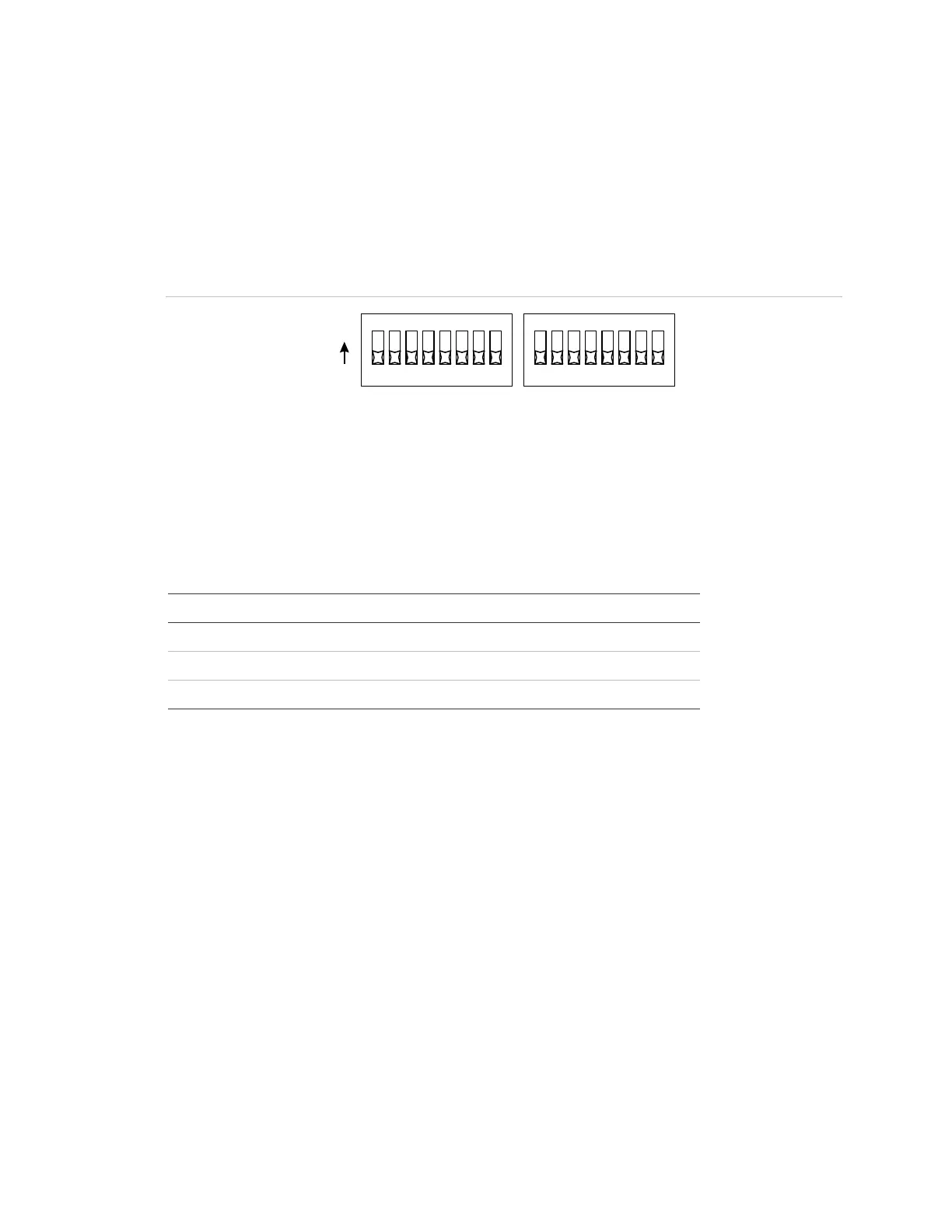
Figure 9: Switch settings
SW1 SW2
1234
5
6
7
8
ON
1234
5
6
7
8
Sense 1 and 2 operation (SW1-1 to 3)
The BPS has three operating modes, as shown in the following table. Switches
SW1-1, -2, and -3 determine which mode is used.
Table 2: Switch settings
Operating mode [1] SW1-1 SW1-2 SW1-3
Correlate mode OFF – –
Genesis Master mode ON OFF ON
Nondelayed mode ON ON –
[1] See the descriptions below for operation details
These switches also determine how Sense 1 and 2 correlate to the NAC circuits.
Details for each mode are described below.
Correlate mode
In correlate mode, switches SW1-2 and SW1-3 control which NACs activate
when the sense circuits activate. The correlations do not affect output circuits
that are operating as AUX circuits.
The following table details which NACs activate when the sense circuits activate.
 Loading...