Remote Booster Power Supply Technical Reference Manual 29
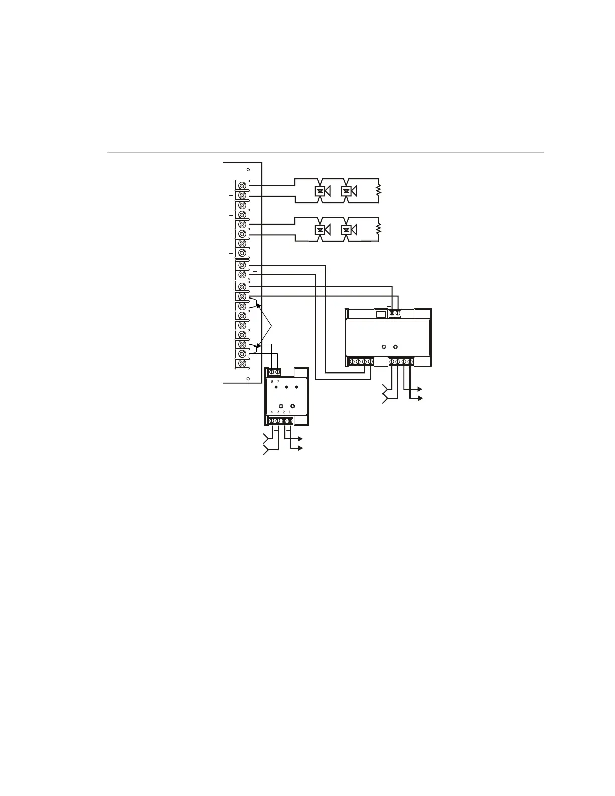
NAC wiring using CC1(S) modules
The following wiring diagrams show Signature Series CC1(S) module
connections. However, other Signature Series signal modules can be used.
Figure 18: Single CC1(S) using the BPS’s 200 mA AUX continuous circuit
+
+
+++
TB2
TB1
TB5
(19)
(18)
+
(17)
4
8
3
7
2
6
10
1
5
9
++
+
+
CC1(S)
CT1
(21)
(20)
++
(1)
(2)
(3)
(4)
(5)
(6)
(7)
(8)
(9)
(10)
(11)
(12)
(13)
(14)
(15)
(16)
(15)
(16)
Legend
(1) NAC1/AUX1
(2) NAC2/AUX2
(3) NAC3/AUX3
(4) NAC4/AUX4
(5) 200 mA AUX Continuous
(6) Sense 1 IN
(7) Sense 1 COM
(8) Sense 1 OUT
(9) Sense 2 IN
(10) Sense 2 COM
(11) Sense 2 OUT
(12) Trouble NO
(13) Trouble COM
(14) Trouble NC
(15) Notification appliance circuit (NAC)
(16) UL listed EOL 15 k
(17) EOL 47 k
(18) Data in from previous device or
Signature controller
(19) Data out to next device
(20) Data in from previous device or
Signature controller
(21) Data out to next device
 Loading...