Remote Booster Power Supply Technical Reference Manual 25
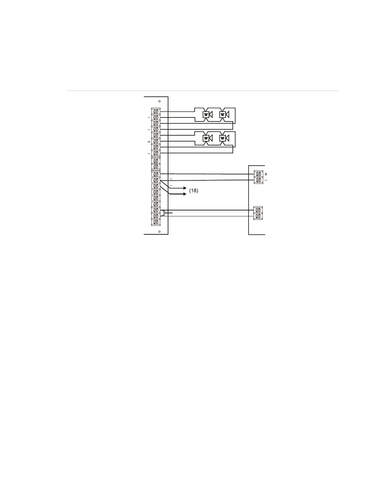
NAC Class A wiring
Connect one NAC circuit to one NAC output, either NAC1 or NAC3. Terminate
the circuit at the NAC2 or NAC4 terminal screw, respectively.
Figure 14: NAC class A wiring
+
++
+++
TB2
TB1
TB5
(1)
(2)
(3)
(4)
(5)
(6)
(7)
(8)
(9)
(10)
(11)
(12)
(13)
(14)
(17)
(19)
(15)
(16)
(20)
(21)
Legend
(1) NAC1/AUX1
(2) NAC2/AUX2 (return for NAC1)
(3) NAC3/AUX3
(4) NAC4/AUX4 (return for NAC3)
(5) 200 mA AUX Continuous
(6) Sense 1 IN
(7) Sense 1 COM
(8) Sense 1 OUT
(9) Sense 2 IN
(10) Sense 2 COM
(11) Sense 2 OUT
(12) Trouble NO
(13) Trouble COM
(14) Trouble NC
(15) Notification appliance circuit (NAC)
(16) Notification appliance circuit (NAC)
(17) Input from signaling circuit
(18) To next booster, or NAC returning to
existing control panel
(19) EOL for IDC circuit
(20) Control circuit source
(21) AC power fail monitoring
Note: The AC power failure panel connection annunciates at the panel but does not report off
premises for a predetermined time in US fire applications. See Table 8 on page 19.
 Loading...