EasyManuals Logo

UTC Fire and Security Edwards BPS10A User Manual

UTC Fire and Security Edwards BPS10A
64 pages
To Next Page IconTo Next Page
To Previous Page IconTo Previous Page
Page #16 background imageLoading...
Page #16 background image
10 Remote Booster Power Supply Technical Reference Manual
Installing the circuit board in the enclosure
You may have to remove the circuit board to install the enclosure. Reinstalling
the circuit board in the enclosure must be done with accuracy to avoid causing
ground faults or shorts. The screws and standoffs must be installed correctly and
in the right positions. Use the diagrams below to install the circuit board.
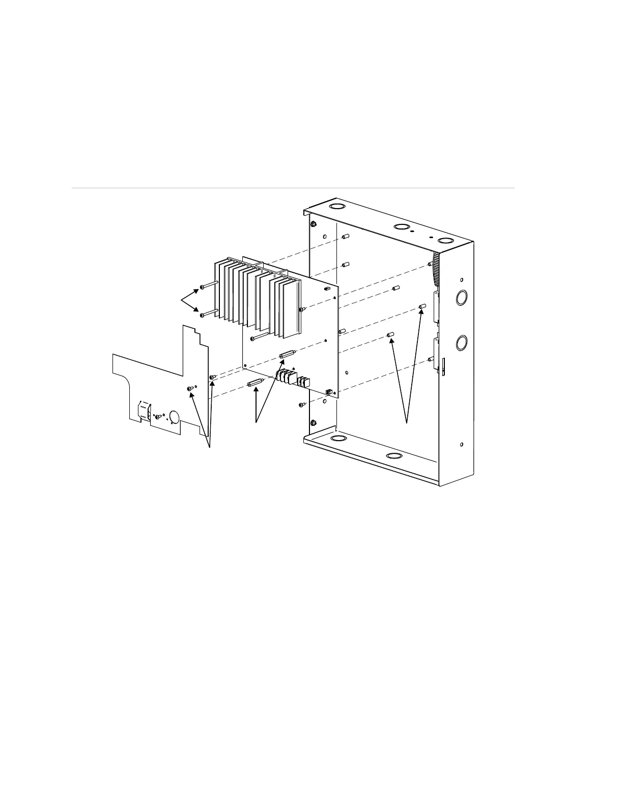
Figure 5: Complete circuit board installation
(4)
(3)
(1)
(6)
(2)
(7)
(5)
(1) Cover (ā€œCā€ models, only)
(2) Long screws
(3) Circuit board
(4) Enclosure
(5) Enclosure standoffs
(6) Barrel spacers, see Figure 6 on page 11
(7) Short screws

Table of Contents

Questions and Answers:

Question and Answer IconNeed help?

Do you have a question about the UTC Fire and Security Edwards BPS10A and is the answer not in the manual?

UTC Fire and Security Edwards BPS10A Specifications

General IconGeneral
BrandUTC Fire and Security
ModelEdwards BPS10A
CategoryPower Supply
LanguageEnglish

Related product manuals