44 Remote Booster Power Supply Technical Reference Manual
Synchronization of visible outputs
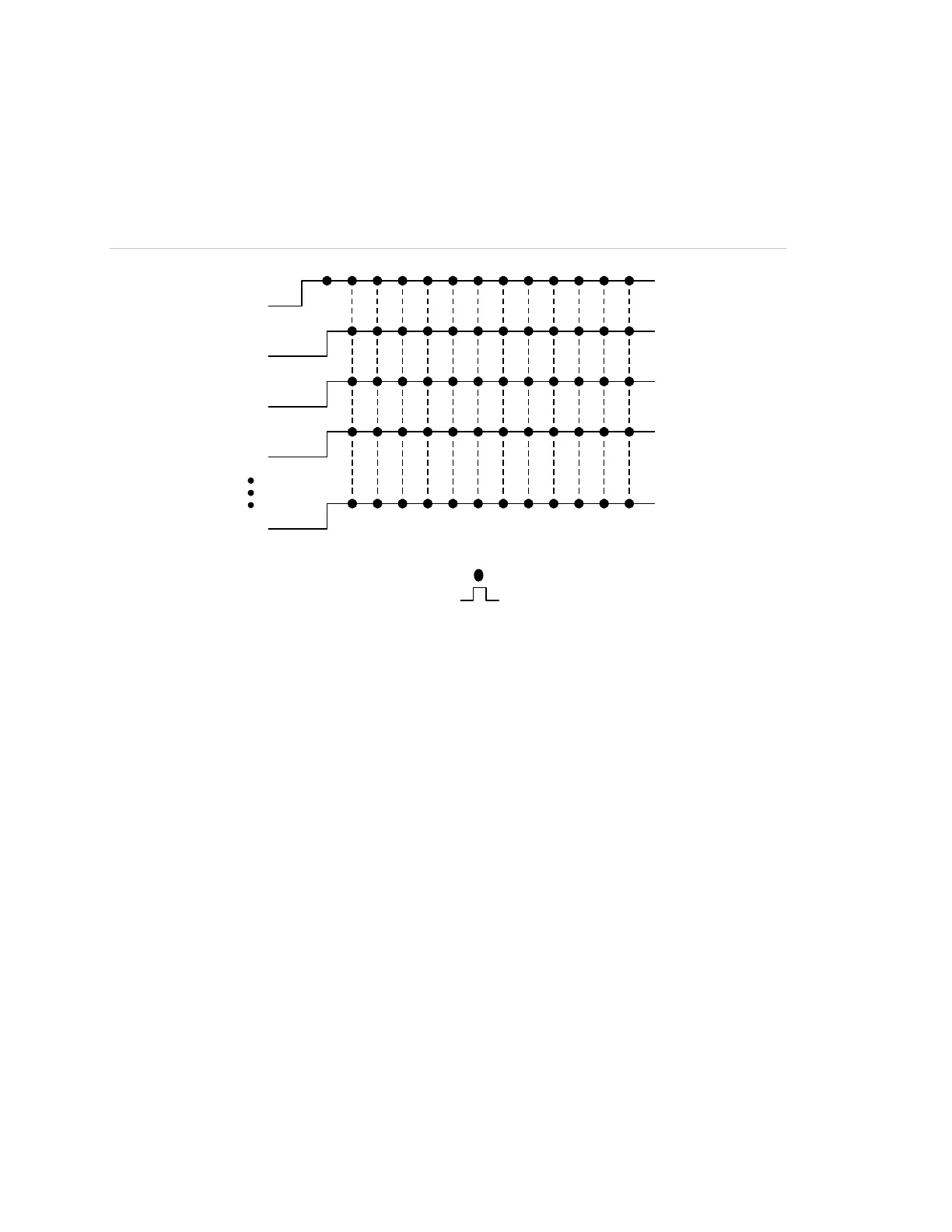
In the figure below, all visible output circuits on each BPS activate with a one
second delay. This requires that the BPSs be connected in parallel through their
sense circuits.
Figure 23: Synchronization with a one second output activation delay
12345678910111213
(1)
(2)
(3)
(4)
(5)
(1) On Sense Off
(2) Output booster 1
(3) Output booster 2
(4) Output booster 3
(5) Output booster n
Sync diagram key
Strobe flash
Audible tone
Synchronization of visible and audible outputs
One-second delay of outputs
In the figure below, all visible and audible circuits are synchronized with a one
second output activation delay when the BPSs are connected in parallel through
their sense circuits.
Note: Delay time is controlled by DIP switch SW1-4. See “Setting the DIP
switches” for more information.