Remote Booster Power Supply Technical Reference Manual 45
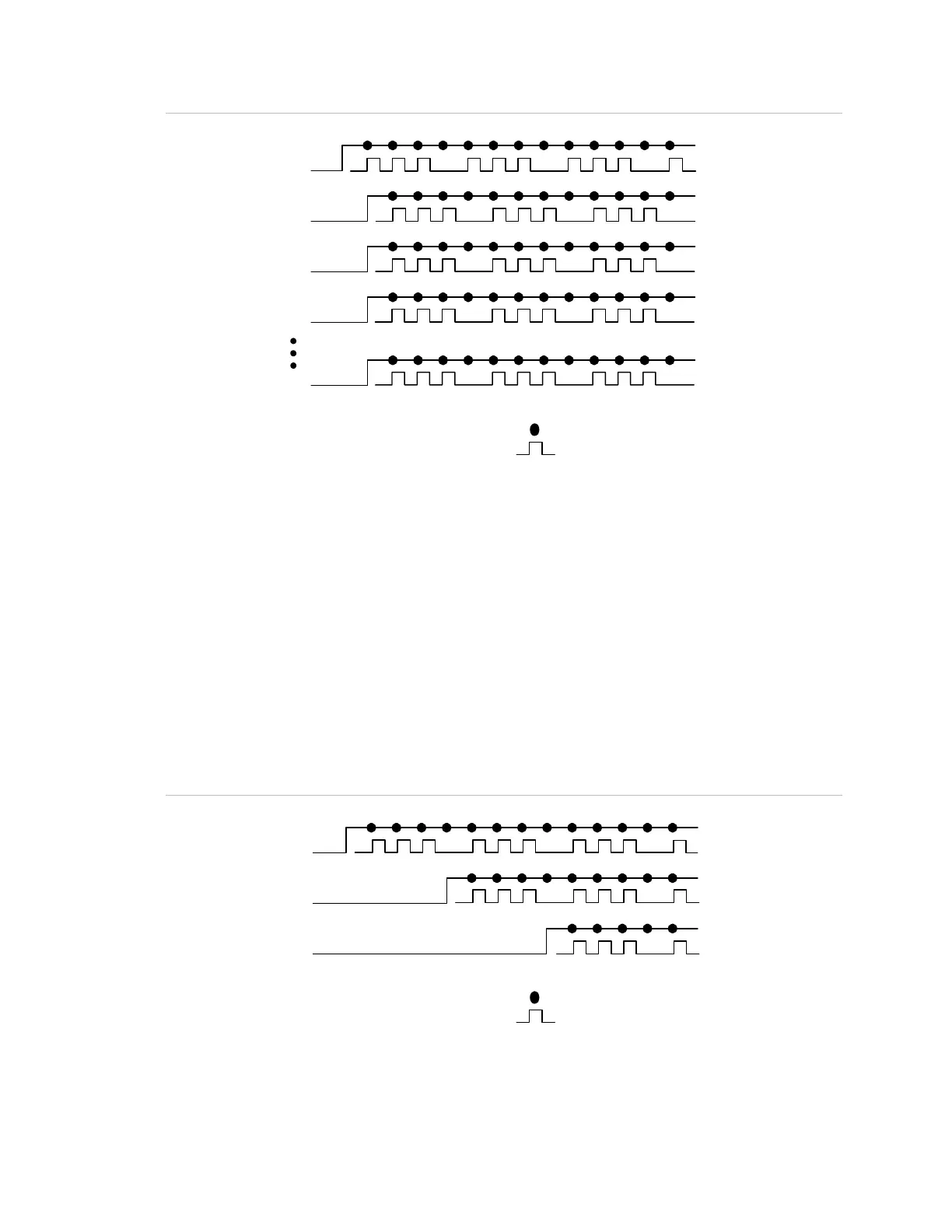
Figure 24: BPSs connected in parallel with sense circuits
12345678910111213
(1)
(2)
(6)
(7)
(5)
(3)
(4)
(6)
(7)
(6)
(7)
(6)
(7)
(6)
(7)
(1) On Sense Off
(2) Output booster 1
(3) Output booster 2
(4) Output booster 3
(5) Output booster n
(6) Visible
(7) Audible
Sync diagram key
Strobe flash
Audible tone
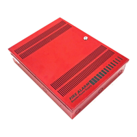
Four-second delay of outputs (temporal setting)
Note: Four-second delay operation does not comply with UL 864 9th edition.
In Figure 25 all visible and audible circuits are synchronized with a four second
output activation delay when the BPSs are connected in parallel through their
sense circuits.
Note: Delay time is controlled by DIP switch SW1-4. See “Setting the DIP
switches” for more information.
Figure 25: BPSs connected in parallel with sense circuits
12345678910111213
(1)
(2)
(3)
(4)
(5)
(4)
(5)
(4)
(5)
(1) On Sense Off
(2) Output booster 1
(3) Output booster 2
(4) Visible
(5) Audible
Sync diagram key
Strobe flash
Audible tone