12 Remote Booster Power Supply Technical Reference Manual
Setting the jumpers
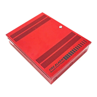
There are four jumpers on the BPS. See Figure 1 on page 4 for the location of
the jumpers.
NAC Class A or Class B (JP1 and JP2)
JP1 and JP2 are used to select a Class A or Class B NAC wiring configuration
for all NACs. The default is Class B.
Note: JP1 and JP2 must be positioned to match the SW2-8 DIP switch selection
(Class A or Class B).
Figure 7: JP1 and JP2
(1) (1)
(2) (2)
JP1 JP2
11
22
33
(1) Class A
(2) Class B
Ground fault enable (JP3)
JP3 is used to set the NAC/AUX circuits for ground fault enabled or disabled
operation. The sense inputs are always isolated from local power.
Enabled: Allows the BPS to perform its own ground fault checking. This is the
default position.
Disabled: Disable the BPS's ground fault detection only when the controlling
panel is providing ground fault detection for the BPS output circuits. See
Figure 8 on page 13 for wiring information.