Remote Booster Power Supply Technical Reference Manual 49
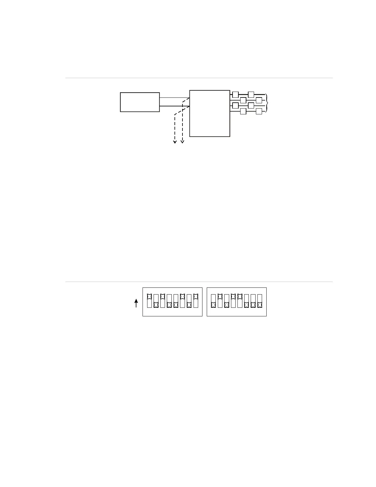
Conventional visible and audible circuit to Genesis
notification
Figure 30: Conventional visible and audible circuit to Genesis notification
G
(1)
(2)
G G
GG
GG
GG
(12)
(11)
G
G G
GG
GG
GG
(3)
(4)
BPS
(7)
(8)
(9)
(10)
(5)
(6)
V/A
(1) NAC visible circuit
(2) NAC audible circuit
(3) Sense 1
(4) Sense 2
(5) Mode: GM
(6) NACs CONT
(7) NAC 1
(8) NAC 2
(9) NAC 3
(10) NAC 4
(11) To next device or EOL resistor
(12) To BPS, or EOL resistor
Note: The maximum number of BPSs that can be connected on a single NAC from sense circuit
to sense circuit is limited by available current and wire run length.
DIP switch settings for this application
BPS DIP switches can be set this way for the application to work correctly. Refer
to “Setting the DIP switches” for other options.
Figure 31: Switch settings
SW1 SW2
1234
5
6
7
8
ON
1234
5
6
7
8