11.4 The Unpopulated 7-Pin Header on the Left (P5)
On the left edge of Witty Pi 4 board, there is another unpopulated 7-pin header, where you can also
solder a male or female connector.
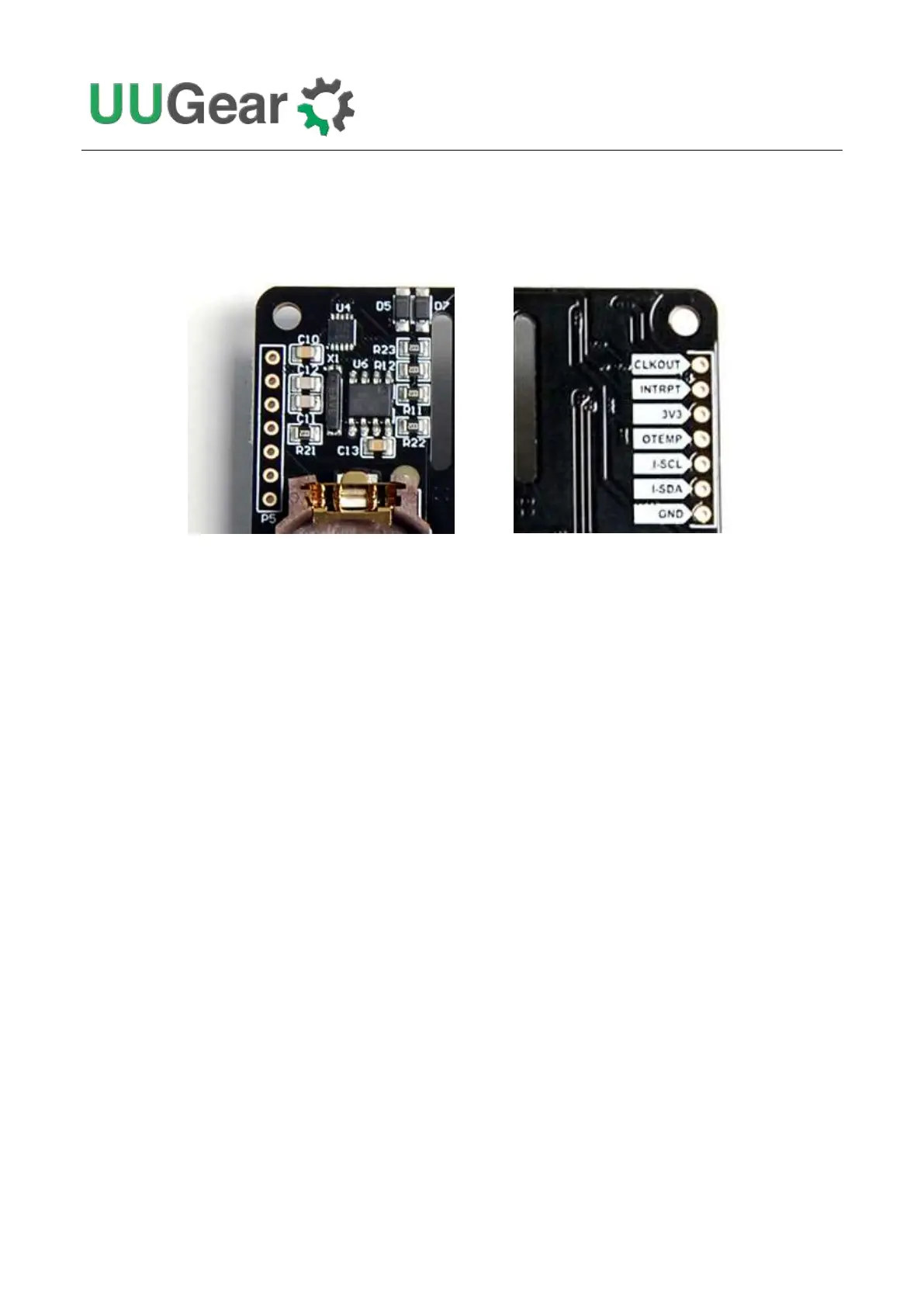
(Front View) (Back View)
This header breaks out the internal I2C bus and also some useful signals.
CLKOUT
This is the 32768Hz clock output signal from the RTC. This signal can be used to calibrate the RTC.
INTRPT
This is the interrupt signal from the RTC, and it is actually the same as the ALM/ALARM pin in
another unpopulated header P3. It goes LOW when alarm is occurred.
3V3
It is 3.3V voltage on Witty Pi 4 board that powers the micro controller, RTC and temperature sensor.
It has nothing to do with the 3.3V pin in Raspberry Pi’s GPIO header. It is the same as 3V3 in P3.
OTEMP
This pin is at HIGH (3.3V) level by default. It goes to LOW (~0V) level when the current temperature
exceeds the preset over-temperature threshold. It will go back to HIGH level when the current
temperature drops under the below-temperature threshold.
I-SCL and I-SDA
These are the SCL and SDA for internal I2C bus. The RTC and temperature sensor are directly
connected to this internal I2C bus.
GND
It is the ground of Witty Pi 4 board, and it directly connects to the GND wire of power supply.