11. Additional Interfaces
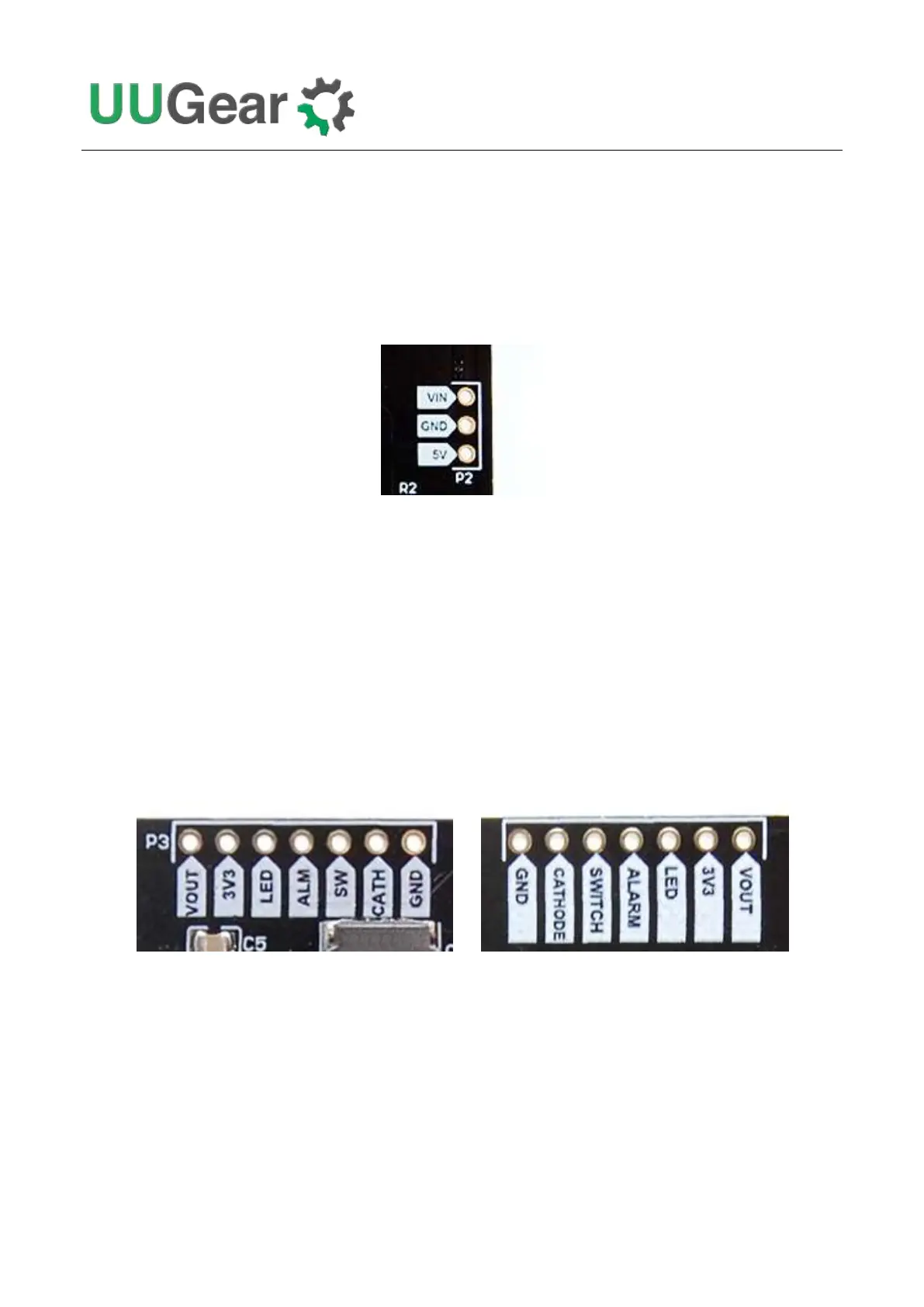
11.1 The Unpopulated 3-Pin Header (P2)
On the right edge of Witty Pi 4 board, there is an unpopulated 3-pin header, and you can solder a
male or female connector here.
This header is for inputting voltage to power Witty Pi. It will be useful if you neither want to input 5V
via the USB Type C connector, nor input higher voltage via the XH2.54 connector.
You can either input 5V between the “5V” and GND pins, or input higher voltage between the “VIN”
and “GND” pins.
11.2 The Unpopulated 7-Pin Header on the Top (P3)
On the upper edge of Witty Pi 4 board, there is an unpopulated 7-pin header, and you can solder a
male or female connector here.
(Front View) (Back View)
This header breaks out some useful signals and is very helpful for extension and integration. The
pins from left to right (at top view) are VOUT, 3V3, LED, ALARM, SWITCH, CATHODE and GND.
VOUT
This pin is actually connected to the +5V pin in Raspberry Pi’s GPIO header, which is also the output
voltage of Witty Pi 4 board. You can also know whether your Raspberry Pi is in ON state by
measuring this voltage.