ENGLISH
46
E
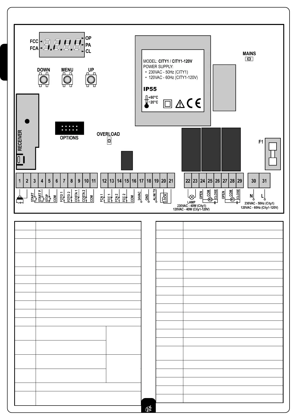
LECTRIC CONNECTIONS TABLE
1 Antenna
2 Antenna shield
3
Opening control for the connection of control
devices with N.O. contact
4
Opening controls for pedestrian access for the
connection of control devices with N.O. contact
5 Stop command. N.C. contact
6 Common (-)
7 Photocells type 1. N.C. contact
8 Photocells type 2. N.C. contact
9 Safety ribbons type 1 (fixed). N.C. contact
10 Safety ribbons type 2 (mobile). N.C. contact
11 Common (-)
12
End of stroke in door 1
opening phase. N.C. contact
13
End of stroke in door 1
closing phase. N.C. contact
14
End of stroke in door 2
opening phase. N.C. contact
15
End of stroke in door 2
closing phase. N.C. contact
16 Common (-)
17 - 18
Power output 24 VAC for photocells and other
accessories
18 - 19 Photocell TX power supply for functional test
20 - 21 Electric lock 12VAC
22 - 23
Flashing light 230VAC 40W (CITY1)
120VAC 40W (CITY1-120V)
24 Motor 2 opening
25 Motor 2 common
26 Motor 2 closing
27 Motor 1 opening
28 Motor 1 common
29 Motor 1 closing
30 Neutral 230 VAC / 120 VAC
31 Power phase 230 VAC / 120 VAC
F1 5A (CITY1) / 8A (CITY1-120V)
OPTIONS Optional modules connector
MAINS It shows that the control unit is power supplied
OVERLOAD
It shows that there is an overload on accessories
power supply
FCC It shows the opening end of stroke activation
FCA It shows the closing end of stroke activation
OP Opening in progress
PA Pause (gate opened)
CL Closing in progress
Encoder
motor 2
(CITY1-ECD only)
Encoder
motor 1
(CITY1-ECD only)