92077r14
www.vac.se
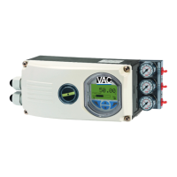
V200 POSITIONER
2
1 INTRODUCTION .................................................................................. 4
1.1 Principle of Operation .............................................................. 4
1.2 ProductIdentication ............................................................... 4
1.3 Safety Instructions ................................................................... 4
2 FEEDBACK INSTALLATION .............................................................. 5
2.1 Connections ............................................................................ 5
2.2 Front cover and indicator ........................................................ 5
2.2.1 Removing the front cover ........................................................ 5
2.2.2 Removing the indicator ........................................................... 5
2.3 4-20mA Transmitter installation ............................................... 6
2.3.1 Gearwheel installation ............................................................. 6
2.3.2 Potentiometer installation ........................................................ 6
2.3.3 4-20mA Transmitter setup ....................................................... 7
2.3.4 Connecting the control signal .................................................. 7
2.3.5 4-20mA Transmitter Calibration ............................................... 8
2.3.6 Trouble shooting - Reset and Calibration ................................ 8
2.4 Switch option installation ......................................................... 9
2.4.1 Switch and cam installation ..................................................... 9
2.4.2 Electrical installation ................................................................ 9
2.4.3 Switch calibration .................................................................... 9
3 SPARE PARTS ................................................................................... 10
3.1 Exploded drawing feedback options ....................................... 10
3.2 Spare parts list feedback options ............................................ 11
4 SPECIFICATIONS............................................................................... 12
4.1 Specicationsfeedbackoptions .............................................. 12
CONTENTS