92077r14
www.vac.se
V200 POSITIONER
6
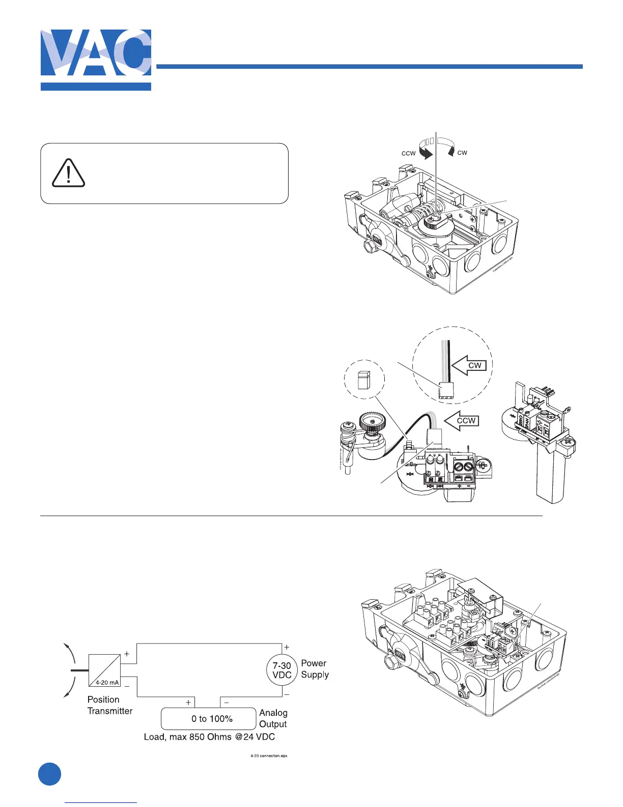
2.3.3 4-20mA transmitter setup
1. Determine the direction for
increasingmAoutput.Direct(CCW)
orReverse(CW).
2. The direction of rotation is simply
determined by watching the positioner
driveshaft(1).
3. CCW rotation: the potentiometer lead
connector(2)ttedwiththeBlackorBlue
colored lead facing to the left.
4. CW rotation: the potentiometer lead
connector(2)ttedwiththeBlackorBlue
colored lead facing to the right.
The position transmitter can be calibrated in a
range from 25° up to 115°.
25°-70°withJumper(3).
70°-115°noJumper(3).
The Position Transmitter is
shipped for direct (CCW)
turning, range 0-90°
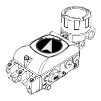
2.3.4 Connecting the control signal
1. Connect the signal cable to the proper
poleontheterminalblock(1).
MaximumcablesizeAWG13(2.5mm
2
)
1
1
2
2
3