92077r14
V200 POSITIONER
www.vacaccessories.com
9
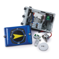
2.4 Switch option Installation
2.4.1 Switch and cam installation
1. Remove the front cover and indicator
ontheV200positioner.(seepage4)
2.RemovetheIndicatorscrew(1).
3.Installtheswitchcamassembly(2)inthe
positioner drive slot and secure the cams with
screw(3).Installtheswitchmodule(4)and
tightenthethreescrews(5).
2.4.2 Electrical installation
Connectyourcontrolsystem/equipmentcables
totheterminalblocks(6)
MaximumcablesizeAWG11(4mm
2
)
2.4.3 Switch calibration
The switch activating points can be adjusted by
turningthefrictionloadedcams(7,8)usingascrew-
driver in the slots on the cams.
1.Withameter,settherstcamtoeithernormally
open(NO)ornormallyclosed(NC)atitsdesired
position.
2.Strokethevalve/actuatortothedesired
position for the second switch and adjust
the second cam.
3. Double check the two activation points.
NOTE: Use a non magnetic screwdriver when
adjusting reed switch cams!
3
1
8
7
6
4
5
2