92077r14
www.vac.se
V200 POSITIONER
4
2. FEEDBACK INSTALLATION
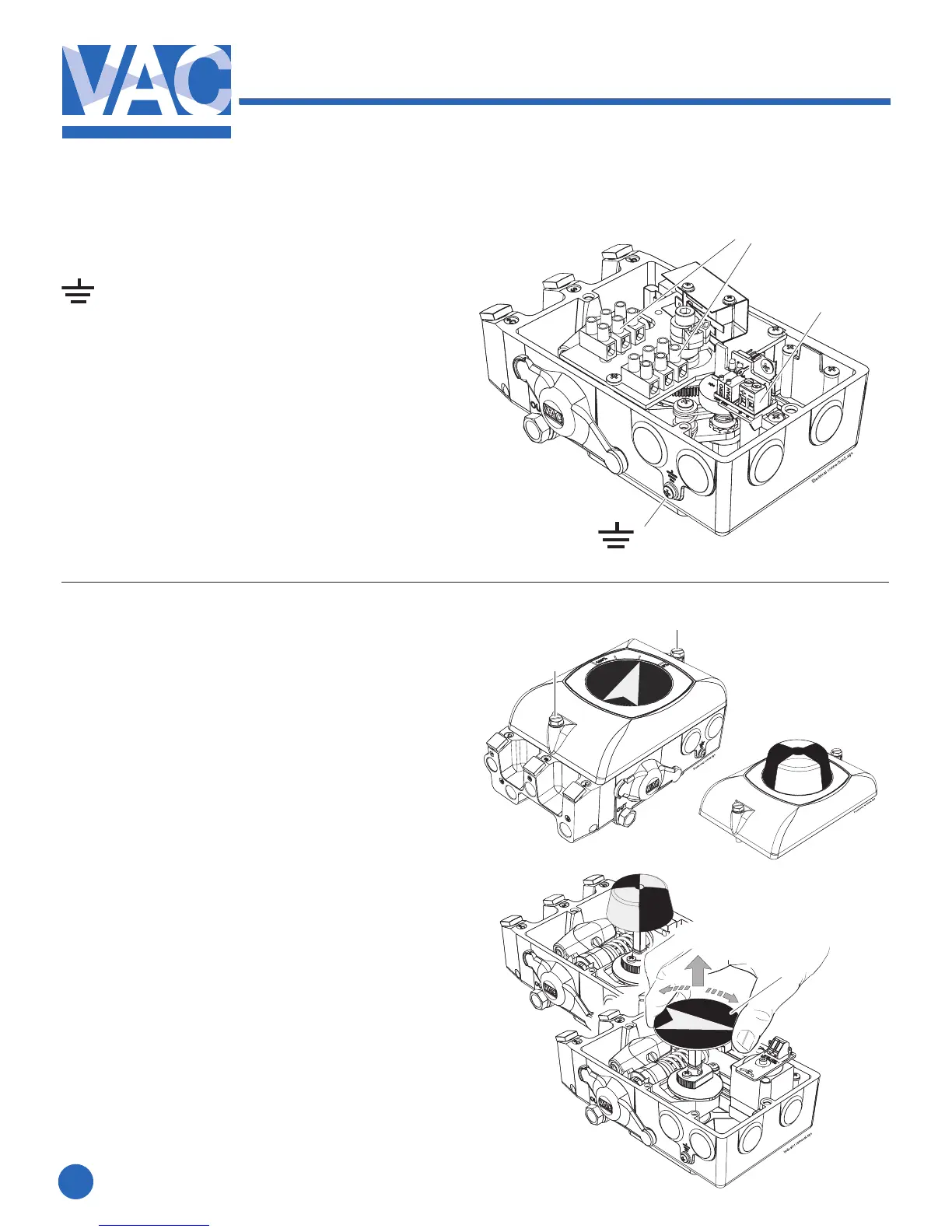
2.1 Connections
– Grounding point
1. – Terminal block, switches
2 X 3 Connections
MaximumcablesizeAWG11(4mm
2
)
2. – Terminal block, Position Transmitter
MaximumcablesizeAWG13(2.5mm
2
)
1
1
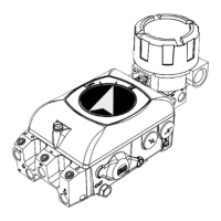
2.2 Front cover and indicator
2.2.1 Removing the front cover
Loosenthetwoscrews(1)and
remove the front cover.
2.2.2 Removing the indicator
Pulltheindicator(2)straightup,itisafrictiont.
Important Note!
Note the indicator’s position so it
can be installed in the same position.
Installing the indicator
Install the indicator in place over the drive
shaft and press it straight down.
Be sure to press the indicator completely down
so that it does not interfere with the indicator
cover(clearcover).
Turn the indicator to the proper display
position.
2
1
2