Do you have a question about the VAC D500 and is the answer not in the manual?
Details the PositionMaster EDP300's integral mount design, modular structure, and performance ratio.
Provides details on downloading additional documentation and alternative ways to access information.
Provides general instructions for installation, commissioning, maintenance, and modifications.
Explains the structure of warnings (DANGER, WARNING, CAUTION, NOTICE) and their meanings.
Specifies the device's purpose and lists examples of incorrect usage.
Emphasizes operator responsibility for network security and states warranty void conditions.
Explains Ex name plate and lists ATEX/IECEx certificates and markings.
Details mounting in explosive atmospheres and cable gland specifications.
Provides operational points for flammable gases and combustible dust areas.
Details T6 operation safety and display legibility at various temperatures.
Provides electrical data for Signal Circuit (AI), Digital Input (DI), Digital Output (DO) for Ex i.
Lists electrical data for various option modules for Ex i.
Provides electrical data for Signal Circuit (AI), Digital Input (DI), Digital Output (DO) for Ex n.
Lists electrical data for various option modules for Ex n.
Explains Ex name plate and lists FM/CSA approvals and classifications.
Details mounting in hazardous areas and cable gland specifications.
Provides operational points for flammable gases, dust areas, and T6 class safety.
Discusses display legibility limits and device functioning guarantees at various temperatures.
Provides electrical data for Signal Circuit (AI), Digital Input (DI), Digital Output (DO) for FM/CSA.
Lists electrical data for various option modules for FM/CSA.
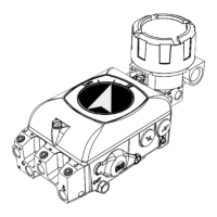
Illustrates the basic device components and optional upgrades with numbered connections.
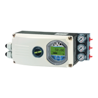
Explains the EDP300 as an electronically configurable positioner for pneumatic actuators.
Describes the information found on the positioner's name plate with numbered fields.
Provides guidelines for inspecting, handling, and storing the device.
Lists ambient conditions and directs users to return procedures.
Warns about injury risk from incorrect parameter values and emphasizes resetting to factory settings.
Explains the use of remote sensors, specifying cable requirements and mounting considerations.
Details general mounting considerations, including operating ranges for linear and rotary actuators.
Provides component lists and installation steps for mounting on linear actuators.
Details mounting procedures on cast iron yokes and columnar yokes, including height adjustment.
Explains actuator bolt positioning and how to adjust the stroke range.
Illustrates integral mounting and mounting with adapter plates on control valves.
Describes mounting the adapter on the positioner and the positioner onto the actuator.
Warns about explosion risk with communication interface and injury risk from live parts.
Shows connection diagrams and terminal assignments for the basic device and options.
Lists connections for remote sensor and notes on explosive atmospheres.
Details electrical specifications for set point signal, digital input/output, and option modules.
Provides electrical specifications for the emergency shutdown function and limit switches.
Explains device connections, cable gland use, and wire cross-sectional areas.
Details wire cross-sectional areas and multi-wire connection capacities for modules and limit switches.
Shows connection diagram for EDP300 Control Unit with Remote Sensor and specifies cable requirements.
Provides instructions for connecting the positioner and remote sensor, including grounding and pneumatic connections.
Shows connection diagram for EDP300 Control Unit with remote position sensor and specifies cable requirements.
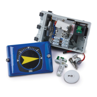
Details steps for installing option modules, including safety notes and checks.
Provides steps to install the mechanical position indication, including shaft extension.
Details installing mechanical feedback and pressure option, with safety precautions.
Describes setting the mechanical position indication, including housing cover and label.
Guides on setting limit switches with proximity switches, including adjusting metal tags.
Explains setting limit switches with 24 V microswitches, including connecting the microswitch.
Details pneumatic connections, including air quality, damage notices, and actuator types.
Advises on compliance with name plate data, environmental conditions, and securing against startup.
Describes checking mechanical mounting by moving the actuator to end positions and performing Auto Adjust.
Details moving the actuator to end positions after Auto Adjust and for new devices, checking recommended ranges.
Warns about injury risk from incorrect parameters and emphasizes factory reset before Auto Adjust.
Explains how to operate the device using the LCD display and operating buttons.
Describes the three menu levels: Process display, Information, Operating modes, and Configuration.
Explains the LCD display information and how to adjust process values.
Details how to navigate to the information level to display diagnostics and operator pages.
Explains how to display and change operating modes, including Adaptive and Fixed control.
Guides on configuring and starting the Auto Adjust function for actuator type selection.
Explains how to preset Autoadjust Mode and view Auto Adjust progress.
Describes tabular entry for selecting and changing parameter values.
Details how to set numerical parameter values by entering decimal positions.
Explains error message structure, groups, and areas, with a note on troubleshooting.
Shows and describes parameters for Easy Setup, Device Setup, Display, and Controller menus.
Details parameters for Digital Input, Alarm Output, Analog Feedback, and Digital Feedback.
Details parameters for Communication, Diagnosis, and Universal Input.
Details parameters for Device Info and Service (Mode, Factory Setting, Sensors, etc.).
Describes Easy Setup parameters including Language, Actuator Type, Bolt Position, Vent Position, Tight Shut, Control, DB Approach.
Defines Autoadjust Mode options and how to start the Auto Adjust function.
Describes Device Setup parameters for actuator, setpoint, ranges, and end stop behavior.
Describes Setpoint Range Min/Max, Filter, and Ramp Up/Down parameters.
Describes SP Charact. Curve for signal adjustment and SP Direction for output relationship.
Describes Valve Rng Calib., Upper Valve Rng, and Lower Valve Rng for valve control range.
Describes Upper Working Rng and Lower Working Rng to configure the working range.
Describes Tight Shut, Control, and Dead Angle settings for end position behavior.
Describes Language, Engineering Units, Display Value selection, and Contrast adjustment.
Describes Zone, Dead Band, DB Approach, DB Control time, and DB Close-Up Range.
Describes KP Up and KP Down for adjusting the controller's proportional gain.
Describes Y-Offset Up and Y-Offset Down for signal offset adjustment.
Details parameters for Digital Input, Alarm Output, Analog/Digital Feedback, and Universal Input.
Describes DI Function, DI Default SP, and DI Logic for digital input activation and configuration.
Describes Alarm Output and Analog Feedback parameters for alarm logic, masking, simulation, and feedback.
Describes Switch 1 parameters: Funct., Value, Logic, Active, Mask Map, Sim.
Describes SW 1 Mask Map and SW 2 Mask Map for alarm classification and simulation.
Describes Switch 2 and Universal Input parameters for limit signals and input configuration.
Describes HART Version selection and Find Device function.
Describes Diagnosis parameters: Partial Stroke, Histogram, Travel Counter, Movement Counter, Reset.
Describes Partial Stroke parameters: PS Configuration, PS Interval, and PS Start Now.
Describes Device Info parameters: Hardware Rev., Software Rev., Mounting Date, Device Address, Pneumatic Type, Stroke Time.
Describes Service Mode, Factory Setting, Adjust Sensors, and Pneumatic settings.
Describes Service parameters: Remote Sensor, Sensor Type, Sensor Calib., Sensor Position, AO Alarm Current.
Explains how to navigate to the information level to view detailed error descriptions.
Lists common error messages, their causes, troubleshooting steps, and groups.
Lists common error messages, their causes, troubleshooting steps, and groups.
Lists common error messages, their causes, troubleshooting steps, and groups.
States the positioner requires no maintenance under normal conditions and emphasizes fault-free operation.
Specifies that repair activities must be done by authorized personnel using original spare parts.
Provides notes on product disposal according to WEEE Directive and specialist recycling.
Details rotation angles, travel limits, and time prolongation for rotary and linear actuators.
Lists output signals, action based on set point, and characteristic curve data.
Provides ambient temperature ranges and directs to ABB's download area for documentation.
Lists optional extension modules, mounting material, pressure gauge blocks, PC adapters, and software.
Provides a statement form for contamination of devices and components for repair/maintenance.
Details hazardous and non-hazardous area classifications, intrinsic safety parameters, and warnings.
Provides notes on natural gas operation, electrostatic charging, and specific requirements for hazardous areas.
Illustrates connection diagrams for Digital Input/Output and Universal Analog Input for hazardous/non-hazardous areas.
Illustrates connection diagrams for Digital Feedback and Emergency Shutdown Module.
Illustrates connection diagrams for Analog Feedback and Limit Switches, referencing NAMUR sensors.
Details notes and requirements for operating the EDP300 with natural gas, including venting and safety.
| Brand | VAC |
|---|---|
| Model | D500 |
| Category | Valve Positioners |
| Language | English |