13
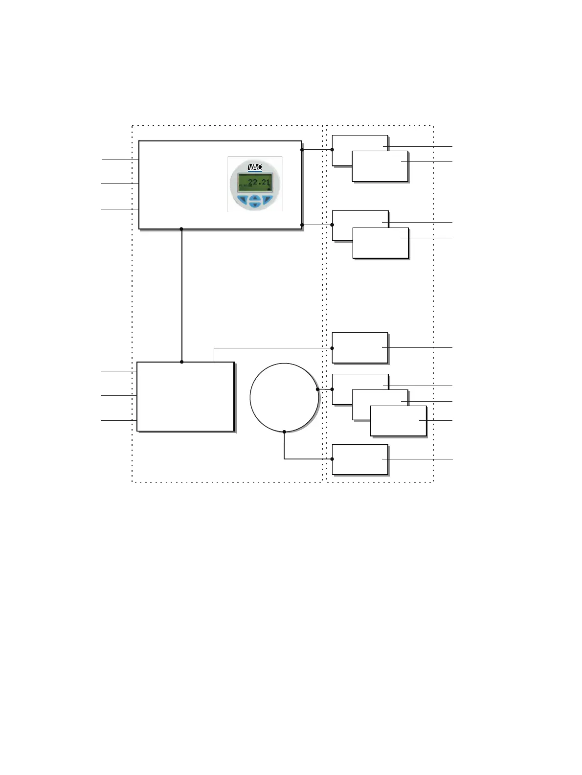
4 Design and function
Schematic diagram
Basic device Optional upgrades
M
A
B
C
2
9
k
l
m
n
o
3
4
5
1
6
7
8
j
A Electronics
B Pneumatics
C Position sensor
1 4 to 20 mA / Bus connection
2 Digital input
3 Alarm output
4 Supply air
5 Output 1
6 Output 2
7 Analog feedback
8 Digital feedback
9 Emergency shutdown module
j Universal input
k Pressure sensor
l Limit alarm with 24 V microswi
tch
m
Limit alarm with proximity switch (N
C)
n
Limit alarm with proximity switch (N
O)
o Visual position indication
Figure 1: Schematic diagram of the positioner