33
Electrical connection
Connect the positioner (EDP300 Control Unit) and remote
position sensor while observing the following instructions:
•
A shielded 3-wire cable with a maximum leng
th of 10 m
(33 ft) must be
used for the co
nnection.
•
Route the cable into the terminal compartment thro
ugh
the EMC
cable glands. Ensure
that the shielding is
se
cured correctly in the EMC cable gla
nds.
•
Connect the cables in accordance
with the electrical
connections and tighten the s
c
rews of the terminals so
that they
are hand-tight
.
• The
electrical connections of the EDP300 Control Un
it
and the optional
modules are carried out as described in
chapter Connection on the device on page 36
.
•
Use wire end ferrules when connecting.
•
If the EDP300 Control Unit is fastened so that it is it non-
conductive, the housing must be ground
ed
(EDP300 Co
ntrol Unit and remote position sensor
with
the
same electric potential); otherwise control devia
tions
could o
ccur with regard to an
alog position feedback.
•
If the device is being operated on a cylind
er, for reasons
associat
ed with linearity you should run automatic
adjustment for the rotary actuat
or.
•
The pneumatic outputs to the actuator
must be
connect
ed using pneumatic lines with a
minimum
diamet
er of 6 mm.
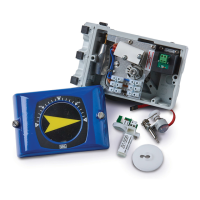
Installing the option modules
Note
The supply voltage must be switched off before the option
modules are installed.
1. Loosen the screws for the housing cover and remove
it.
2. Position the option module so that the plug points to the
right.
3. Using a small
amount of pressure, guide the
option module
into the slot from the side
an
d press it down firmly.
4. Secure the option module in t
he housing by ti
ghtening the
screw so that it is hand-tight.
5. Attach the ho
using cover and screw it on to the ho
using.
Tighten the screws so th
at they are hand-tig
ht.
6. If you
are using the emergency shutdown module, the rota
ry
switch on the
main printed circuit board must be rotate
d
into position 1
using a suitable flat-bladed screwdriver.
7. Attach the housing cover and screw it on to the ho
using.
Tighten the screws so th
at they are hand-tig
ht.
Note
A ma
ximum of two option modules may be used at the same
time. The module types must be different.
Note
If you are using the emergency shutdown module, the module
must be supplied with 24 V DC at terminals +85 / Æ86.
Otherwise, the positioner will not be able to function
pneumatically (device in pneumatic safety position).
Note
Perform a functional check of the emergency shutdown module
(option) at least every 2 years. For this purpose, the positioner
must move the valve into the safety position when the 24 V DC
signal (terminal +85 / Æ86) is interrupted.
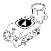
Installing the mechanical position indication
1. Loosen the screws for the housing cover and remove it.
2. Attach the shaft extension to the shaft and secure it using
the sc
rew provided.
3. Attach the round position indication to the shaft ext
ension
a
nd rotate it into the desired position.
4. Set the new housing cover (with round sight
glass) and screw
it on to the ho
using. Tighten the screws so that they ar
e
hand
-tight.