36
… 7 Installation
Pneumatic connections
Note
The positioner must only be supplied with instrument air that is
free of oil, water, and dust (in gas configuration with dried
natural gas).
The purity and oil content must meet the requirements of Class
3 according to DIN/ISO 8573-1.
NOTICE
Damage to components!
Contamination on the air pipe and positioner can damage
components.
• Dust, splinters, and any other particles of dirt must be
blown-out before the pipe is connected.
NOTICE
Damage to components!
Pressure above 10 bar (145 psi) can damage the positioner
or actuator.
• Provisions must be made, e.g. by using a pressure
reducer, to make sure that the pressure does not rise
above 10 bar (145 psi), even in the event of a fault.
Information on double acting actuators with spring-
return mechanism
On double-acting actuators with spring-return mechanism, a
pressure that significantly exceeds the supply air pressure value
can be generated during operation by the springs in the
chamber opposite the springs.
This may damage the positioner or adversely affect control of
the actuator.
To eliminate the possibility of this occurring, it is recommended
to install a pressure compensation valve between the springless
chamber and the supply air for these types of applications. It
enables the increased pressure to be transferred back to the air
inlet line.
The opening pressure of the check valve should be < 250 mbar
(< 3.6 psi).
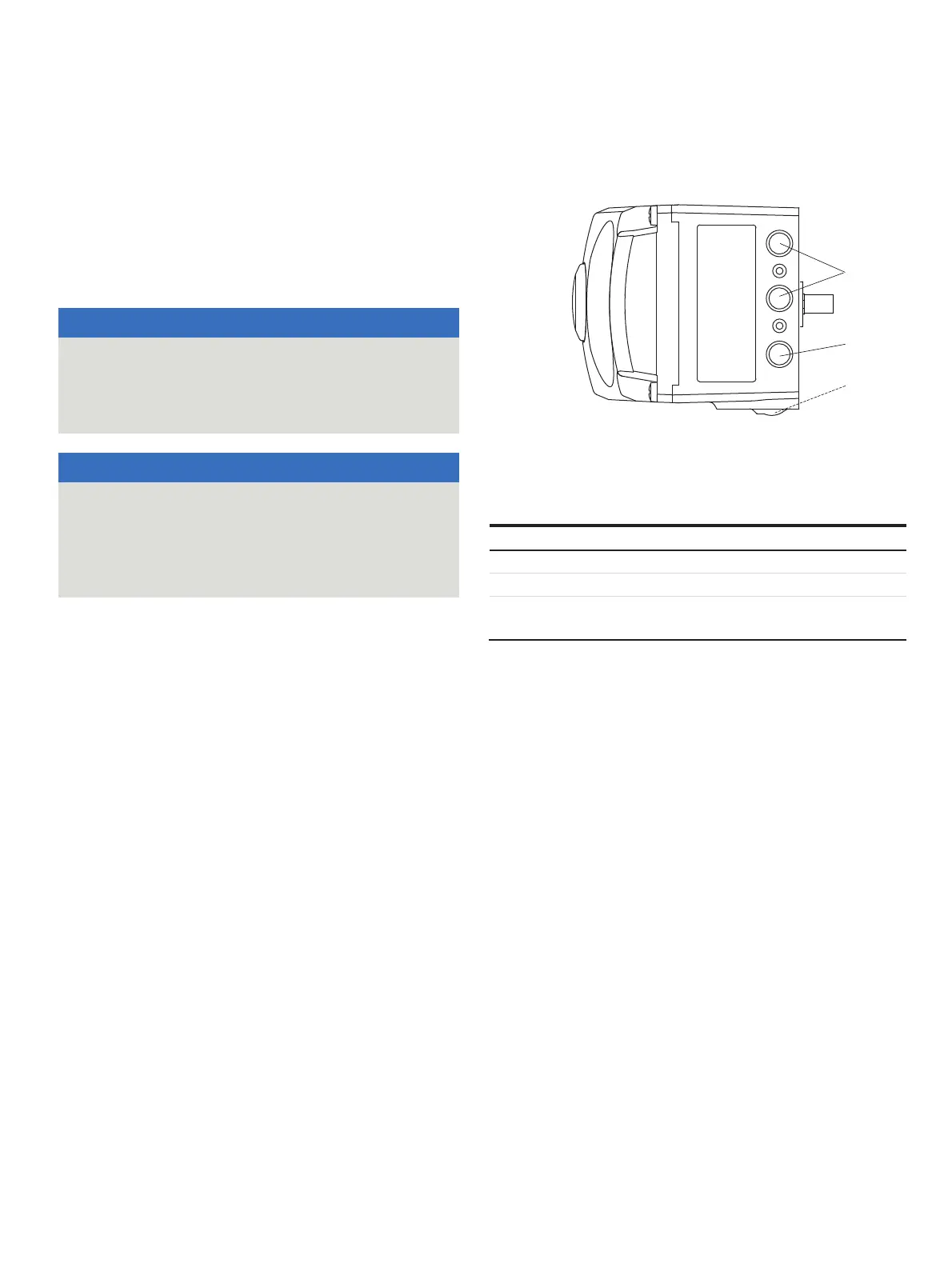
Connection on the device
M10132-01
2
3
NPT1/4"
G1/4"
Y2
2OUT
Y1
1OUT
SUP ZUL/
IN
1
1 Pneumatic outputs
2 Supply air
3 Filter screw (on underside of
housing)
Figure 27: Pneumatic connections
Marking Pipe connection
SUP / ZUL IN Supply air, pressure 1.4 to 10 bar (20 to 145 psi)
Y1 / OUT1 Output pressure to the actuator
Y2 / OUT2 Output pressure to the actuator
(2 Connection with double acting actuator)
Join the pipe
connections according to the designation,
observing the following points:
•
All pneumatic piping connections are
located on the
right-hand side of the positioner. G¼ or ¼ 1
8
NPT tap
holes
are provided for the pneumatic connections. The
positioner is labeled according to the tap holes available.
•
We recommend that you use a pipe with di
mensions of
12 × 1.75 mm. The supp
ly air pressure req
uired to apply
the act
uating force must be adjusted in line
with the
output pressure in the
actuat
or.
•
The operating range of the
positioner is between
1.
4 to 10 bar (20 to 145 psi).