34
… 7 Installation
… Installing the option modules
Installing the mechanical position feedback
1. Loosen the screws for the housing cover and remove it.
2. If one h
as been installed, remove the optical
position
indication and
unscrew the shaft ext
ension.
3. Move the print
ed circuit board for position feedb
ack to the
right underneath the t
wo plastic clips and secure it using th
e
screw provided.
4. .If appli
cable, install th
e optical position indication.
5. Attach the ho
using cover and screw it on to the ho
using.
Tighten the screws so th
at they are hand-tig
ht.
Installing the pressure option
CAUTION
Risk of injury
Risk of injuries due to flying components as well as significant
noise emissions.
• Prior to disassembly, all connected compressed air lines
must be depressurized.
Note
•
The supply voltage must be switched off before the pressu
re
option is installed
.
•
The bonding wires for the
pressure option must not be
touched.
Doing so will cause damage to the
option module.
•
Before using the device, a high-voltage test in accord
ance
with
IEC must be performed.
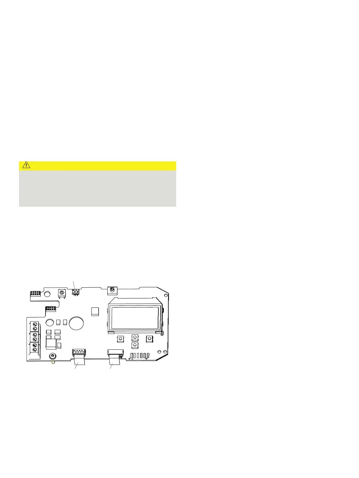
M10144-01
1
23
1 I/P converter pneumatic system
2 Position sensor
3 Pressure option
Figure 25: Printed circuit board
1. Loosen the screws for the housing cover and remove it.
2. Loosen all
cable connections on the screw te
rminals.
3. If present,
unscrew the option modules and
remove them
from the side.
4. If present,
remove the
mechanical position indication and
scre
w off the shaft extension (as well as the mechanic
al
al
arm signaling unit if applicable).
5. Remove the screws for the plastic cover and remove th
e
cover.
6. Remov
e both plug connectors from the print
ed circuit board.
7. Unscrew the fixing screws for the print
ed circuit board
and
caref
ully remove the printed
circuit board.
8. Unsc
rew the screws on the upper side of the pneumatics an
d
remove th
e cover plat
e.
9. Carefully
attach the pressure option to
the pneumatics and
scre
w it in place so that the screws are hand-t
ight.
10.Install the print
ed circuit board.
11. Attach both plug connectors
1, 2 to the printed circuit
boa
rd (see Figure 25)
.
12. Attach the plug connectors for the pressure option
3 to the
printed circuit
board (see Figure 25)
.
13. Attach the plas
tic cap
.
14. If nec
essary, install option modules and set the mechanic
al
feedb
ack.
15. Attach the housing cover and screw it on to the ho
using.
Tighten the screws so th
at they are hand-tig
ht.
Setting the option modules
Setting the mechanical position indication
1. Loosen the screws for the housing cover and remove it.
2. Rotate the pos
ition indicator on the shaft to
the desired
position.
3. Attach the housing cover and screw it onto the ho
using.
Tighten the screws so th
at they are hand-tig
ht.
4. Attach th
e symbol label to mark the minimum and ma
ximum
valv
e positions on the ho
using cover.
Note
The labels are located on the inside of the housing cover.