30
… 7 Installation
… Electrical connections
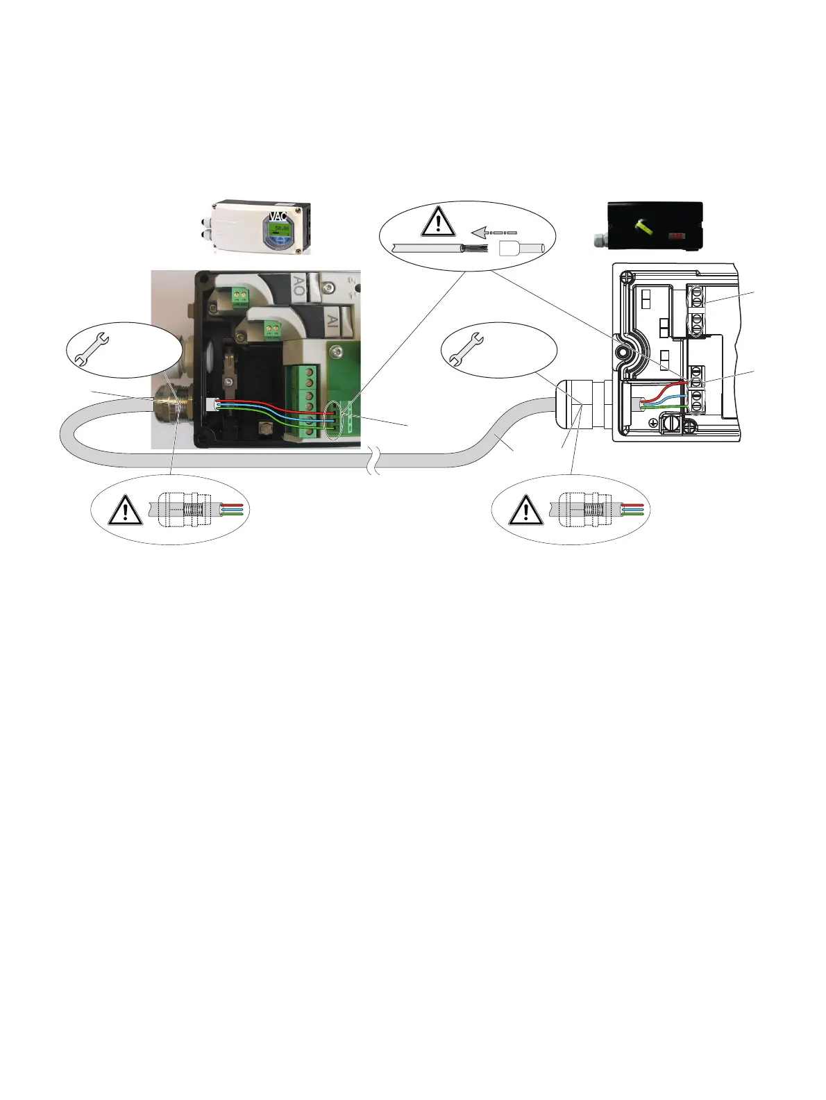
Connection to device - EDP300 Control Unit with EDP300 Remote Sensor
Housing 1 (EDP300 Control Unit) Housing 2 (EDP300 Remote Sensor)
M10832-01
+41 -42
Limit 2
Limit 1
+51 -52
1 2 3
1
1
4 3
3
2
M 20 mm /
NPT 1/2"
M 20 mm /
NPT 1/2"
1 Terminals EDP300 Remote Sensor
2 Terminal attachment kit for digital feedback
3 EMC Cable gland
4 Shielded connection cable
Figure 23: Connection EDP300 Control Unit with EDP300 Remote Sensor (example)
Change from one to tw o columns
In the case of the ‘EDP300 Control Unit with EDP300 Remote
Sensor’ design, the components are supplied in two housings,
which together form one harmonized unit.
Housing 1 (EDP300 Control Unit) contains the electronics and
pneumatics along with the following optional modules (where
applicable):
•
Analog position feedba
ck
•
Digital position feedba
ck
•
Emergency shutdown module
• Univers
al input
Housing 2 (EDP300 Remote Sensor) contains the position sensor
and is suitable for mounting on linear or rotary actuators.
If necessary, the following options can be installed if required:
• Optical position indicator
• Mechanical
feedback contacts designed as
proximity
switch
es or microswitches
.
The ho
usings of the EDP300 Control Unit and the EDP300
Remote Sensor are available in stainless steel as an option.
Cable specification
To connect the EDP300 Remote Sensor, a cable with the
following specifications needs to be used:
•
3-wire, cross-section 0.5 to 1.0 mm
²
•
Shielded, with at least 85 % coverage
•
Temperature range up to at least 100 °C (212 °F)
The cable glands used must also be approved for a temperature
range up to at least 100 °C (212 °F). The cable glands require a
mounting for the shielding and strain relief for the cable in
addition.
ABB offers suited cables and cable glands with DNV_GL
certification for the EDP300 Remote Version.