31
Electrical connection
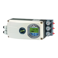
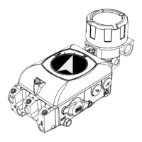
Connect the positioner (EDP300 Control Unit, housing 1) and
remote position sensor (EDP300 Remote Sensor, housing 2),
while following the instructions below:
•
The EDP300 Remote Sensor and the EDP300 Control
Unit
ar
e adjusted to each other. Ensure that only devices
with
the sa
me serial number are connected.
•
A shielded 3-wire cable with a maximum leng
th of 10 m
(33 ft) must be
used for the co
nnection.
•
Route the cable into the terminal compartment thro
ugh
the EMC
cable glands. Ensure
that the shielding is
se
cured correctly in the EMC cable gla
nds.
•
Connect the cables in accordance
with the electrical
connections and tighten the s
c
rews of the terminals so
that they
are hand-tight
.
•
Use wire end ferrules when connecting.
• The
electrical connections of the EDP300 Control Un
it
and the optional
modules are carried out as described in
chapter Connection on the device on page 36
.
•
If the EDP300 Control Unit is fastened so that it is it non-
conductive, the housing must be ground
ed
(EDP300 Co
ntrol Unit and EDP300 Remote
Sensor
housing with the s
ame electric potential); ot
herwise
control d
eviations could occur with regard to an
alog
position fe
edba
ck.
—
In the EDP300 Remote Sensor in IP rating IP 66, pre-
tighten the cover screws by applying approx. 50 Ncm
(0.44 lbf-in) cross-wise and then tighten by applying
200 Ncm (1.77 lbf-in).
•
The pneumatic outputs to the actuator
must be
connect
ed using pneumatic lines with a
minimum
diamet
er of 6 mm.
C
hange from two to one colum n