35
Setting the mechanical limit switch with proximity
switches
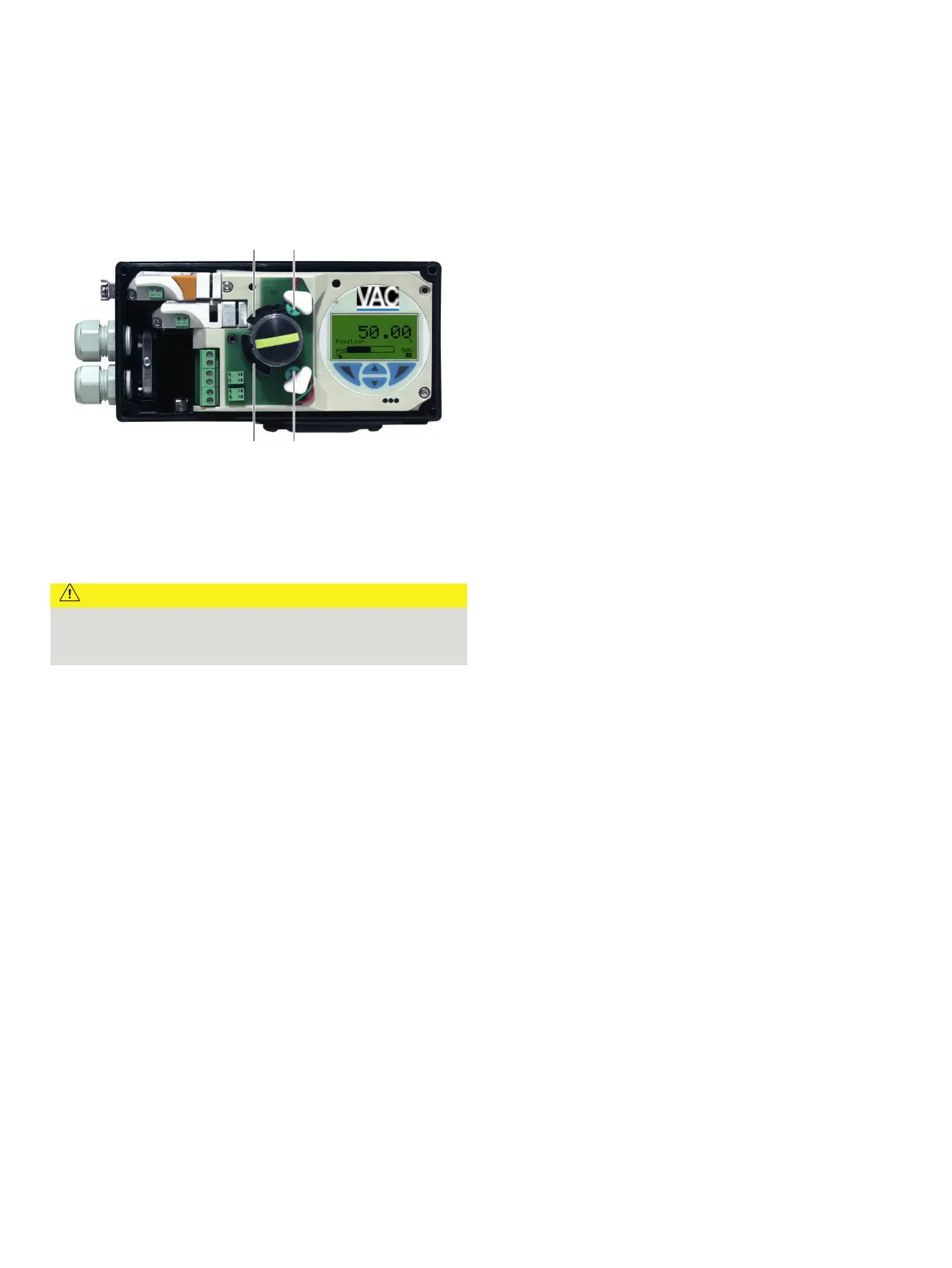
M11020
1 2
4 3
1 Upper metal tag
2 Proximity switch Limit 2
3 Proximity switch Limit 1
4 Lower metal tag
Figure 26: Limit switch with proximity switches
1. Loosen the screws for the housing cover and remove it.
CAUTION
Risk of injury!
The device includes slot sensors with sharp edges.
• Adjust the metal tags using a screwdriver only!
2. Set the upper and lower switching points for binary feedback
as follows:
•
Select the ‘Manual Adjustment’ operating mode and mov
e
the final cont
rol element by hand into the lo
wer switching
position.
•
Using a screwdriver, adjust the metal ta
g of proximity
switch 1 (lo
wer contact) on the axis until contact is ma
de,
i. e
., just before it is inserted in the proximity switch. The
slot sensor enters proximity switch 1 when the feedback
shaft is rotated clockwise (as viewed from the front).
•
Move the final control element by hand into the
upper
switching position.
•
Using a screwdriver, adjust the metal ta
g of proximity
switch 2 (
upper contact) on the axis until contact is made
,
i. e
., just before it is inserted in the proximity switch. The
slot sensor enters proximity switch 2 when the feedback
shaft is rotated counter-clockwise (as viewed from th
e
front).
3.
Attach the housing cover and screw it onto the ho
using.
4.
Tighten the screws so that they are hand-tig
ht.
Setting the mechanical limit switch with 24 V
microswitches
1. Loosen the screws for the housing cover and remove it.
2. Select th
e ‘Manual Adjustment’ operating mode and mov
e
the final cont
rol element by hand into the de
sired switching
position for co
ntact 1.
3. Set maximum contact (
1, lower washer).
Fasten the upper washer with the special adj
ustment
ret
ainer and rotate the lower washer manually.
4. Select the ‘Manual Adjustment’ operating mode and mov
e
the final cont
rol element by hand into the de
sired switching
position for co
ntact 2.
5.
Set minimum contact (
2, upper washer);
Fasten the lower washer with the special adjustment retaine
r
a
nd rotate the upper washer manually.
6. Connect the mi
croswitch.
7. Attach the ho
using cover and screw it on to the ho
using.
8. Tighten the screws so th
at they are hand-tig
ht.