18
… 7 Installation
… Mechanical mounting
Mounting on linear actuators
For mounting on a linear actuator in accordance with DIN / IEC
534 (lateral mounting as per NAMUR), the following attachment
kit is available:
M10413-01
1
2
3
4
5
6
7
8
9
j
k
l
m
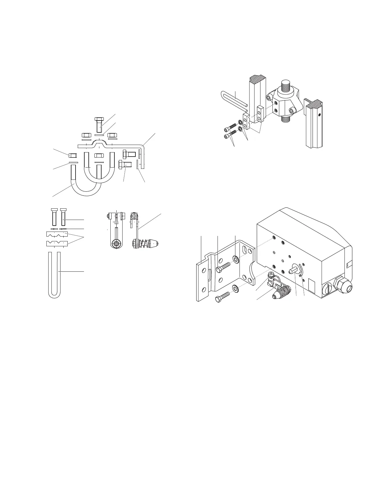
1 Screw
2 Washer
3 Mounting bracket
4 Lever with follower pin for
mechanical stroke 10 to 35 mm
(0.39 to 1.38 in) or 20 to 100 mm
(0.79 to 3.94 in)
5 Washers
6 Screws
7 U-bolts
8 Washers
9 Nuts
j Screws
k Spring washers
l
Cl
amp plates
m Follower guide
Figure 6: Components of attachment kit
M10411-01
1
2
3
4
Figure 7: Attaching a follower guide to the actuator
1. Tighten the screws so th
at they are hand-tig
ht.
2. Attach the follower guide
1 and clamp plates 2 with
screws
4 and spring washers 3 to the actuator stem.
M10409-01
4
5
6
7
12
3
Figure 8: Mounting lever and bracket on the positioner
1. Attach the lev
er
6 to the feedback shaft 5 of the
positioner (can
only be mounted in one posit
ion due to the
cut shape of the
feedback shaft).
2. Using the arrow marks
4, check whether the lever moves
within the op
erating range (between the arro
ws).
3. Hand-tighten the screw
7 on the lever.