19
4. Hold the prepared positioner (with the mount bracket 1 still
loose) on the actuator so that
the follower pin for the lev
er
ent
ers the follower guide to determine which tap holes on
the positioner must be used for the mount bracket.
5. Secure the mount bracket
1 with screws 2 and washers 3
using the relev
ant tap
holes on the positioner housing.
Tighten the screws
as evenly as possible to ensure
subsequent linearity. Align the mount bracket in the oblong
hole to ensure that the operating range is symmetrical (lever
moves between the arrow marks
4).
M10418-01
1234
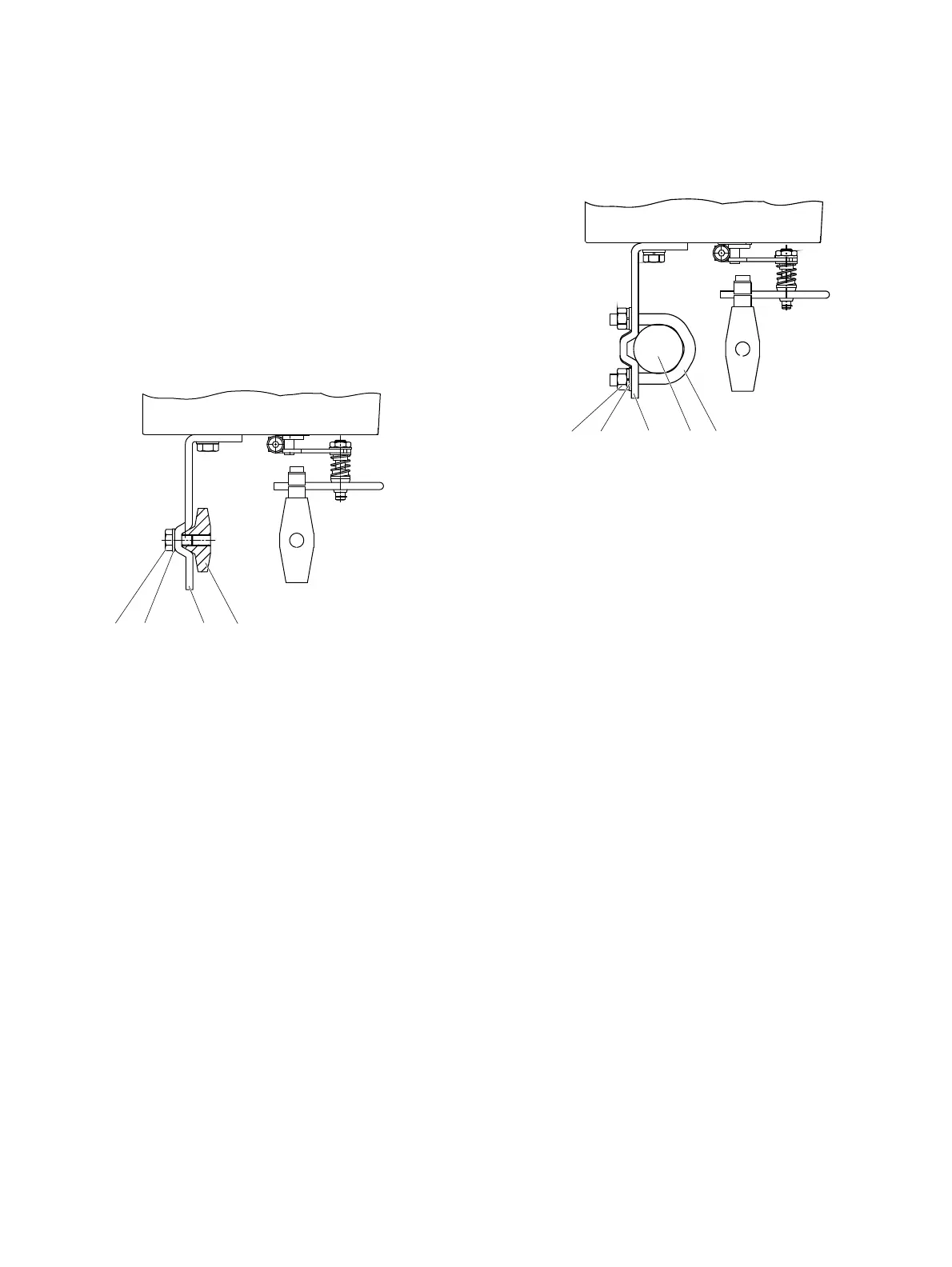
Figure 9: Mounting on a cast iron yoke
1. Attach the mo
unt bracket
2 with screw 4 and washer 3
to the cast iron yoke
1.
or
M10419-01
1
2
3
45
Figure 10: Mounting on a columnar yoke
1. Hold the
mount bracket
3 in the proper position on the
colu
mnar yoke
2.
2. Insert the U-bolts
1 from the inside of the columnar yoke 2
through the ho
les of the mo
unt bracket.
3. Add the
washers
4 and nuts 5.
Tighten the nuts so that they
are hand-tight.
Note
Adjust the heig
ht of the positioner on the cast iron yoke or
columnar yoke until the lever is horizontal (based on a visual
check) at half stroke of the valve.