22
… 7 Installation
… Mechanical mounting
M10424-01
12
3
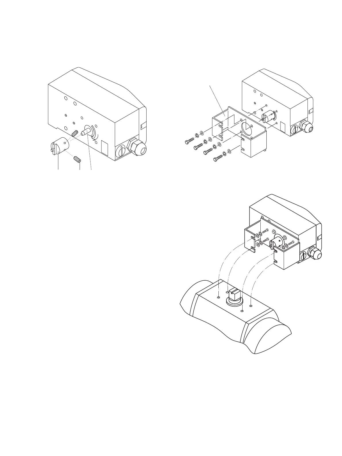
Figure 17: Mounting the adapter on the positioner
1. Determine the mounting position
(par
allel to actuator or at 90° angle)
2. Calculate the rotational di
rection of the actuator
(right or left).
3. Move th
e part-turn actuator into the home po
sition.
4. Pre-
adjust feedback shaft.
To make sure that the positioner runs
within the operating
rang
e (refer to General on page 17), the mounting position as
well as the basic position and rotation direction of the
actuator must be considered when determining the adapter
position on axis
1. For this purpose, the feedback shaft can
be adjusted manually so that the adapter
3 can be attached
in the correct position.
5. Place the adapter in the proper position on the feedback
shaft and fasten with threaded pins
2. One of the threaded
pins must be
locked in place on the flat side of the feedback
shaft.
M10421-01
1
1 Attachment bracket
Figure 18: Screwing the attachment bracket onto the positioner
M10416
Figure 19: Screwing the positioner onto the actuator
Note
After mo
unting, check whether the operating range of the
actuator matches the measuring range of the positioner, refer to
General on page 17.