92077r14
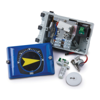
V200 POSITIONER
www.vacaccessories.com
5
2.3 4-20mA transmitter installation
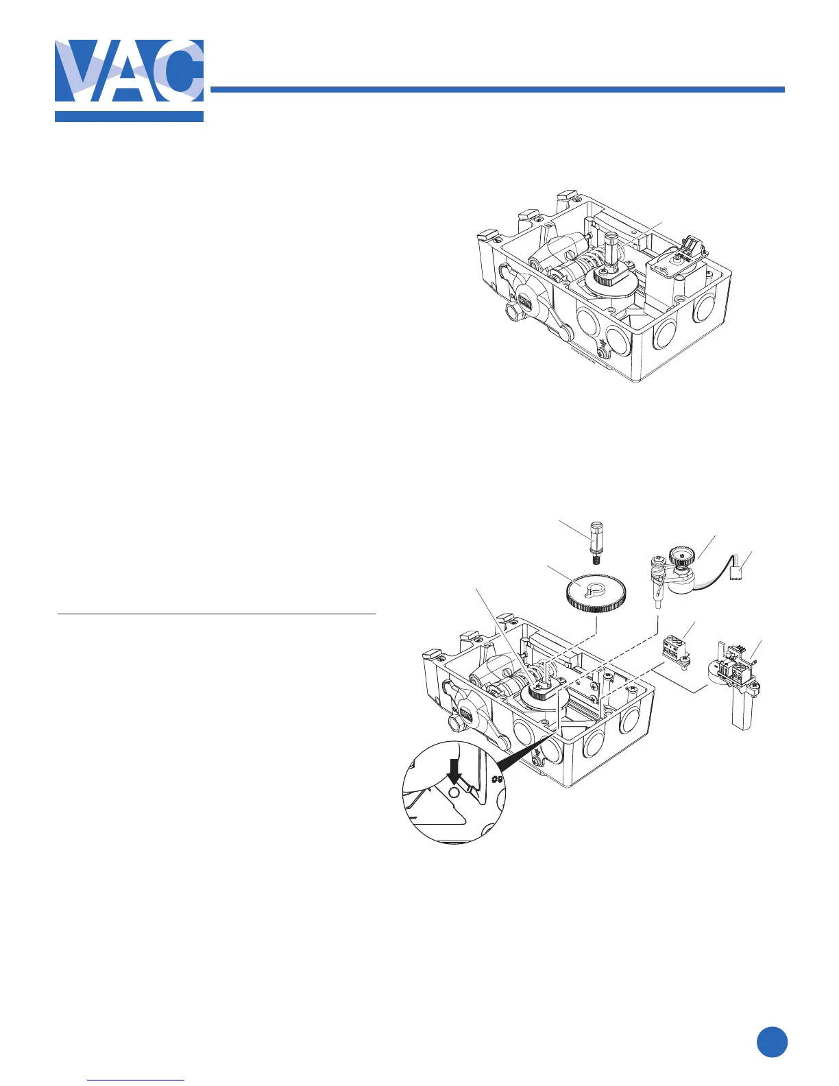
2.3.1 Gearwheel installation
1. Remove the front cover and indicator
ontheV200positioner.(seepage4)
2.RemoveIndicatorscrew(1).
3.Installthegearwheel(2)sothatitalignsover
thecamlockingnutscrew(3).
4. Secure the gearwheel with the
Indicatorscrew(1).
2.3.2 Potentiometer installation
1.Installthepotentiometermodule(4)in
the designed section of the unit as
shown. Tighten the screw that secures
the pot arm and spring.
The pot gearwheel should be aligned
and secured to the larger gearwheel.
2.Installthepotentiometerboard(5)orthe
4-20mAtransmittermodule(6)intothe
designed position and tighten the respective
screws.
3. When used for the 4-20mA feedback, secure
thepotentiometerconnector(7)tothe
transmitter(6).Forpotentiometeruseonly,
theconnector(7)willattachtotheterminal
block(5)andbeusedwithanexternalposition
transmitter.
1
4
3
2
1
5
6
7