Do you have a question about the Vacon NXI and is the answer not in the manual?
Crucial safety warnings regarding electrical hazards and proper handling.
Essential guidelines for safe installation, operation, and maintenance procedures.
Procedures for correct earthing and protection against earth faults.
Steps and symbols for safe motor operation and checks.
Information about CE marking and product compliance with EEA directives.
Details on EMC directive compliance and technical criteria for the inverters.
Explanation of the Vacon NX type designation code structure.
Specific type designation for FI9 to FI14 inverter frames.
Overview of the standard features and specifications of NXI inverters.
Guidelines for proper storage conditions and procedures for the inverter.
Recommendations for routine maintenance to ensure reliable operation.
Details on the warranty period, coverage, and exclusions.
Introduction to the technical data section and inverter block diagram.
Comprehensive tables of power ratings and dimensions for different NXI models.
Specific power ratings for NXI_xxxx 5 series inverters.
Specific power ratings for NXI_xxxx 6 series inverters.
Detailed technical specifications including electrical, environmental, and dimensional data.
Instructions and considerations for physically mounting the inverter unit.
Information on fan cooling requirements and necessary installation space.
Specific mounting space dimensions for FI9 to FI14 inverter frames.
Guidelines for ensuring adequate airflow and ventilation within the enclosure.
Wiring diagrams illustrating power connections for the inverter.
Details on DC supply, motor cables, and required fuses for power connections.
Cable types, material, and specifications for DC supply and motor connections.
Recommended fuse types, sizes, and quantities for NXI_xxxx 5 models.
Recommended fuse types, sizes, and quantities for NXI_xxxx 6 models.
Cable sizing guidelines for inverter supply and motor connections for NXI_xxxx 5.
Cable sizing guidelines for inverter supply and motor connections for NXI_xxxx 6.
Visual representation of terminal sizes for DC supply and motor connections.
Step-by-step instructions for cable installation and routing.
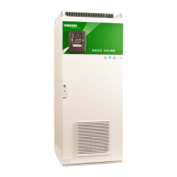
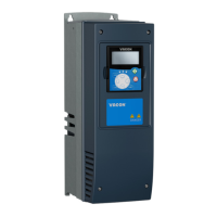
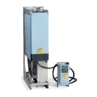
Images showing different Vacon NXI inverter frames.
Requirements for cable installation according to UL standards and terminal torques.
Procedures for testing insulation resistance of cables and motor.
Information regarding the inverter's control unit, boards, and connections.
Details on the wiring of basic I/O and relay boards.
Specifications and tightening torques for control cables.
Explanation of galvanic isolation principles in control connections.
Technical details of control terminal signals on the basic I/O board.
Explanation of various indicators and symbols on the control keypad display.
Symbols and meanings indicating the drive's operational status (RUN, STOP, READY).
Symbols denoting the selected control source (I/O, Keypad, or Fieldbus).
Description of the status indicator LEDs and their corresponding states.
Explanation of the information displayed on the keypad's three text lines.
Identification and overview of the nine push-buttons on the control keypad.
Detailed descriptions of the function of each keypad button.
Guide to navigating through menus and submenus using the keypad.
How to access and use the monitoring menu to view real-time drive data.
Procedure for accessing, viewing, and editing inverter parameters.
Menu for selecting control place, editing frequency reference, and motor direction.
Steps to choose the inverter's control source (I/O, Keypad, or Fieldbus).
Explanation of the STOP button's behavior and how to configure it.
Menu for viewing active faults, codes, and descriptions.
Classification of fault types (Alarm, Fault, Autoreset, Trip).
Detailed list of fault codes, their causes, and corrective actions.
How to access and manage the history of recorded faults.
Menu for system-wide settings such as language, application, and parameters.
Procedure for setting the display language of the control keypad.
How to select and upload different inverter applications.
Functionality for copying parameter sets between the drive and the keypad.
Tool for comparing current parameter values with stored or default ones.
Setting and managing password protection for application and parameter changes.
Customization options for keypad behavior, including default page and timeouts.
Accessing information and parameters related to expander boards.
Critical safety precautions to be followed before and during commissioning.
Step-by-step instructions for the initial setup and commissioning process.
Guide to identifying and resolving faults using fault codes and descriptions.