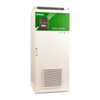
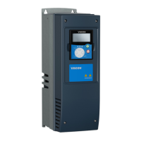
cabling and connections vacon • 55
24-hour support: +358-(0)40-8371 150 • Email: vacon@vacon.com
6.2.2
Control terminal signals
Terminal Signal Technical information
+10 Vref Reference voltage Maximum current 10 mA
AI1+ Analogue input,
voltage or current
Selection V or mA with jumper block X1 (see page
58):
Default: 0– +10V (Ri = 200 kΩ)
(-10V…..+10V Joy-stick control, selected with a jumper)
0– 20mA (Ri = 250 Ω)
GND/AI1– Analogue input common Differential input if not connected to ground;
Allows ±20V differential mode voltage to GND
AI2+ Analogue input,
voltage or current
Selection V or mA with jumper block X1 (see page
58):
Default: 0– 20mA (Ri = 250 Ω)
0– +10V (Ri = 200 kΩ)
(-10V…..+10V Joy-stick control, selected with a jumper)
GND/AI2– Analogue input common Differential input if not connected to ground;
Allows ±20V differential mode voltage to GND
24 Vout
(bidirectional)
24V auxiliary voltage
±15%; maximum current 250 mA all boards total; 150
mA from single board. Can also be used as external
power backup for the control unit (and fieldbus).
GND I/O ground Ground for reference and controls
DIN1 Digital input 1
R
i
= min. 5kΩ
18…30V = "1"
DIN2 Digital input 2
DIN3 Digital input 3
CMA Digital input common A for
DIN1, DIN2 and DIN3.
Must be connected to GND or 24V of I/O terminal or
to external 24V or GND
Selection with jumper block X3 (see page 58):
24 Vout
(bidirectional)
24V auxiliary voltage Same as terminal #6
GND I/O ground Same as terminal #7
DIN4 Digital input 4
R
i
= min. 5kΩ
18…30V = "1"
DIN5 Digital input 5
DIN6 Digital input 6
CMB Digital input common B
for DIN4, DIN5 and DIN6
Must be connected to GND or 24V of I/O terminal or
to external 24V or GND
Selection with jumper block X3 (see page 58):
AO1+ Analogue signal (+output) Output signal range:
Current 0(4)–20mA, R
L
max. 500Ω or
Voltage 0—10V, R
L
>1kΩ
Selection with jumper block X3 (see page 58):
AO1– Analogue output common
DO1 Open collector output Maximum U
in
= 48VDC
Table 6-10. Control I/O terminal signals on basic I/O board OPT-A1